Z80 Emulation on an Arduino, Part 2 – Running MSBASIC

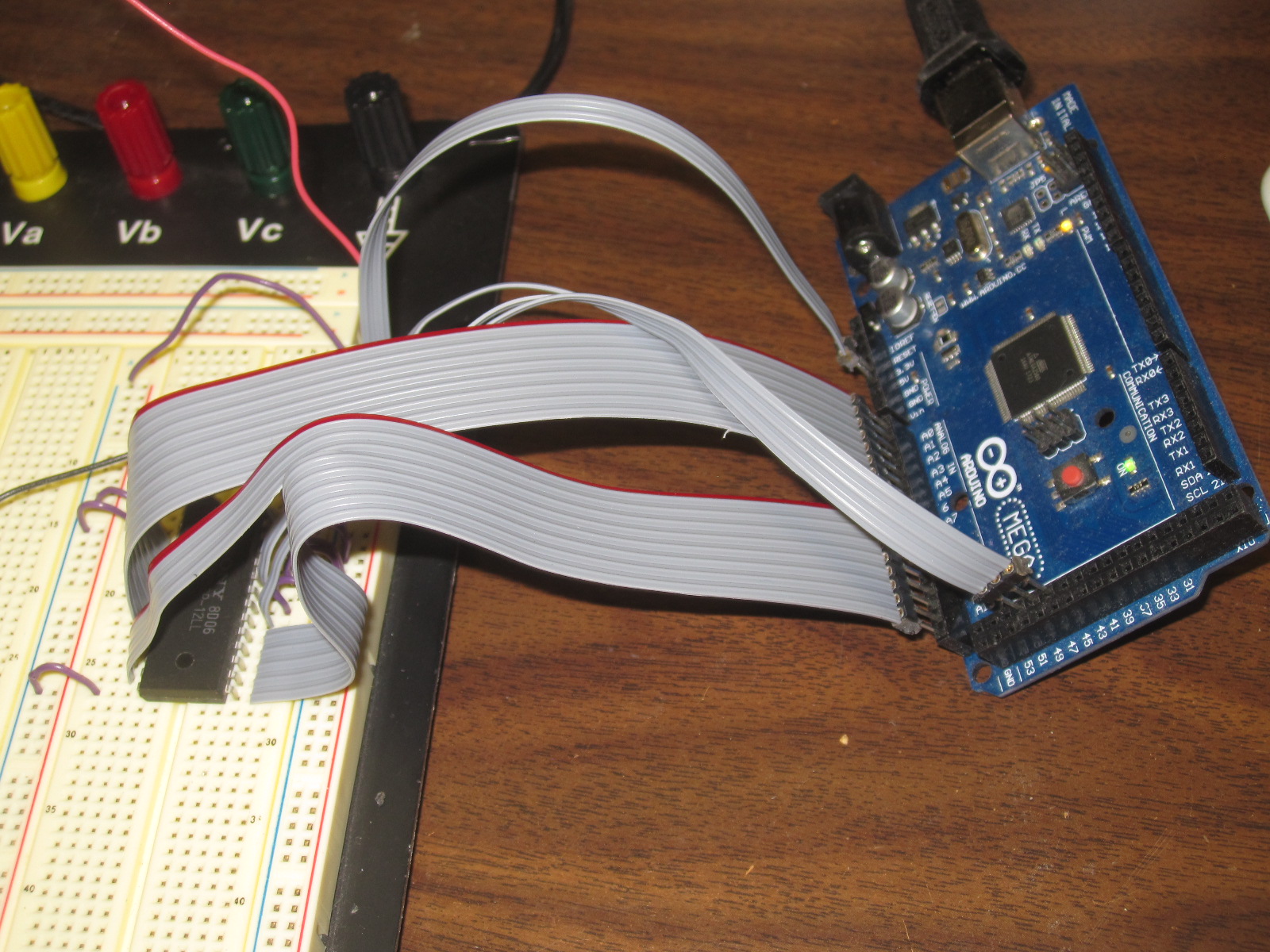
The goal of this project was to get MSBASIC running in an emulated Z80 processor on an Arduino, with no external hardware/components required. Here’s what it looks like when running:

I went with the Arduino Due as it has 96K of RAM, more than enough for a Z80, as well as 512K flash, and a 32-bit ARM core microcontroller running at 84 MHz. Note that the Due uses 3.3V I/O, not 5V as many of the older Arduino boards. Although this will actually be useful for me down the road…

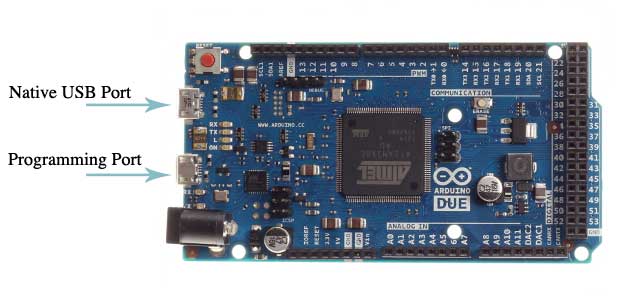
The Due has four serial ports, including two available on USB connectors, the programming port and the native port. I’m using the native port as the terminal interface for the emulated Z80.

For the Z80 emulation I went with z80emu

For MSBASIC itself I went to Grant Searle’s fabulous site, Grant’s 7-chip Z80 computer in particular, and grabbed his ROM files and assembly files.

There’s source code for both a simple monitor that live at 0000H as well as MSBASIC itself which starts at 0150H:
intmini.asm
basic.asm

Also included are the Intel Hex files for both as well as a combined ROM file:
BASIC.HEX
INTMINI.HEX
ROM.HEX

I decided to use the source files and assemble them myself with the asmx multi-CPU assembler, that way I could make changes if I needed to.

I then wrote my own simple little program to take the resulting object code (.bin file) and convert it into Arduino source code that defined a 8K array of PROGMEM prog_uint8_t bytes, which looks like:

const static prog_uint8_t rom_bytes[] PROGMEM = {
0xF3,0xC3,0xB8,0x00,0xFF,0xFF,0xFF,0xFF,0xC3,0x9F,0x00,0xFF,0xFF,0xFF,0xFF,0xFF,
0xC3,0x74,0x00,0xFF,0xFF,0xFF,0xFF,0xFF,0xC3,0xAA,0x00,0xFF,0xFF,0xFF,0xFF,0xFF,
0xFF,0xFF,0xFF,0xFF,0xFF,0xFF,0xFF,0xFF,0xFF,0xFF,0xFF,0xFF,0xFF,0xFF,0xFF,0xFF,
0xFF,0xFF,0xFF,0xFF,0xFF,0xFF,0xFF,0xFF,0x18,0x00,0xF5,0xE5,0xDB,0x80,0xE6,0x01,
0x28,0x2D,0xDB,0x81,0xF5,0x3A,0x43,0x20,0xFE,0x3F,0x20,0x03,0xF1,0x18,0x20,0x2A,
....
0x00,0x00,0x00,0x00,0x00,0x00,0x00,0x00,0x00,0x00,0x00,0x00,0x00,0x00,0x00,0x00,
0x00,0x00,0x00,0x00,0x00,0x00,0x00,0x00,0x00,0x00,0x00,0x00,0x00,0x00,0x00,0x00
};

This was then added to my Arduino project as another file, rom.h. When the emulator starts up, it’s copied to the memory array used by the emulator for memory access in the 8K 0000-01FF range where the ROM lives. I have another 64K memory array for RAM, right now the lower 8K is never access, but eventually I’ll add the ability for the Z80 to swap out the ROM and swap it in, for a full 64K of RAM (via an IO port access), once I get CP/M running, which is another project.

I have some benchmarking code that estimates the effective CPU speed. It adds some overhead, but even with that I get about 7.4 MHz, which is actually pretty close to ideal for a “real” Z80.

Now my code:

The Z80 sketch itself, which gets everything going:


extern "C"{
#include "MyZ80Emulation.h"
};

#include "rom.h"

#include

void setup() {
Serial.begin(9600);

Serial.println("Serial Open");

SerialUSB.begin(9600);
SerialUSB.println("Terminal Open");

pinMode(LED_BUILTIN, OUTPUT);

int i;

Serial.println("Copy ROM");
for (i=0; i<8192; i++) InitEmulationRom(i,pgm_read_byte_near(rom_bytes+i) ); Serial.println("InitEmulation"); InitEmulation(); } void loop() { digitalWrite(LED_BUILTIN, HIGH); EmulateInstructions(); digitalWrite(LED_BUILTIN, LOW); while (SerialUSB.available()>0)
{
int ch;
ch=SerialUSB.read();
if (ch==127) ch=8; // handle delete key
AddToInputBuf(ch);
}

InterruptZ80IfNeeded();
}

void my_putchar(int c)
{
SerialUSB.write(c);
}

MyZ80Emulation.c which interfaces with the actual emulation code:

//
// MyZ80Emulation.c
//
//

#include "MyZ80Emulation.h"

#include
#include
#include "zextest.h"

#define Z80_CPU_SPEED 4000000 // In Hz.
#define CYCLES_PER_STEP (Z80_CPU_SPEED / 40) // let's do 100k cycles
#define MAXIMUM_STRING_LENGTH 100

ZEXTEST context;

void InitEmulationRom(int address, int data)
{
context.rom[address] = data;
}

void InitEmulation(void)
{
context.is_done = 0;
Z80Reset(&context.state);
context.state.pc = 0x0;
}

void EmulateInstructions(void)
{
double totalCycles, totalTime, khz;
unsigned long time1,time2;

time1=micros();
totalCycles += Z80Emulate(&context.state, CYCLES_PER_STEP, &context);
time2=micros();

return; // uncomment if we want to time the system

if (time2>time1) // ignore case where the microseconds timer wrapped around
{
totalTime=time2-time1;
if (totalTime>0) khz = 1000.0 * totalCycles / totalTime; else khz=0;
printf("totalCycles: %6d totalTime: %6d %6d kHz \n",(int)totalCycles,(int)totalTime,(int)khz);
}

}

// Handle user terminal input, characters stored in a circular buffer

inputBuf[256];
inputBufInPtr=0;
inputBufOutPtr=0;

void AddToInputBuf(int c)
{
inputBuf[inputBufInPtr]=c;
inputBufInPtr++;
}

void InterruptZ80IfNeeded(void)
{
if (inputBufInPtr==inputBufOutPtr) return; //only interrupt if there is a received character in the ACIA
int cycles;
cycles=Z80Interrupt (&context.state, 0x38, &context); // interrupt Z80
}

// Emulate 8650 ACIA, port input
int SystemCallPortIn(ZEXTEST *context, int port)
{
int inputReady=0;

if (inputBufInPtr != inputBufOutPtr) inputReady=1;

if (port==0x80) return (0x02+inputReady); // ACIA status register, always ready to transmit, inputReady decdes if we have an input character

if (port==0x81)
{
if (!inputReady) return (inputBuf[inputBufOutPtr]); // no new data, send last character anyway
char c;
c=inputBuf[inputBufOutPtr];
inputBufOutPtr++;
return c;
}

printf("SystemCallPortIn %04x\n", port); // if not handled above, display this diagnostic message

return 0;
}

// Emulate 8650 ACIA, port output
void SystemCallPortOut(ZEXTEST *context, int port, int x)
{
if (port==0x81) // UART write a byte
{
my_putchar(x);
return;
}

if (port==0x80) // ACIA write control register, we never need to handle this
{
return;
}

printf("SystemCallPortOut %04x %02x\n", port, x); // if not handled above, display this diagnostic message

}

\

MyZ80Emulation.h the header for the above:

//
// MyZ80Emulation.h
//
//

#ifndef MyZ80Emulation_h
#define MyZ80Emulation_h

#include

void SetFuncton(int (*f)(void));

void InitEmulationRom(int address, int data);
void InitEmulation(void);
void EmulateInstructions(void);
void my_putchar(int c);
void AddToInputBuf(int c);
void InterruptZ80IfNeeded(void);

#endif /* MyZ80Emulation_h */

Z80 Emulation

My goal is to built a Z80 system along the lines of some of the early CP/M machines. A long long time ago in a far away former life, I worked in industrial controls, and some of the systems were Z80 based. So let’s see how much I still remember.

To get things started, I decided to first go down the emulator route before building any real hardware. I grabbed a copy of z80emu and got it running in xCode in an hour or so. It came with some text ROM files that exercise the emulation, to make sure everything is working correctly.

I found this site: Z80 Monitor Type Operating System and SBC where the author build a very simple Z80 system (Z80, RAM, ROM, 8251 UART).
So for the next step, I got that ROM working in the emulator, and modified the code to route UART output to the stdout. So far so good. Then I kludged something together to read input from XCode’s debug terminal, which also worked. Yay.

Then changing gears a but I wanted to experiment accessing a SRAM chip. I connected a 32Kx8 SRAM to an Arduino Mega 2560 and verified I could write and then read back correctly from several memory locations. This was not emulating a Z80 or
anything, just testing I/O from the Arduino.

KitchenAid Mixer QRM

I discovered a new QRM / RFI source today, my wife’s new KitchenAid 7-Quart Pro Line Stand Mixer. Here’s a waterfall screenshot after it turned on, you can see the roughly 15 kHz spaced bands of interference. These use a DC motor, presumably that is the cause of the RFI, vs mixers with a regular AC motor.

Fortunately she doesn’t use it that often, and she’s testing out a new low carb dough recipe, so I can live with it. Speaking of low carb, here’s our low carb pizza recipe.

The Squid – A Universal Matching Transformer for Beverage, Longwire, Dipole, Random wire, K9AY, Flag, EWE… and More Antennas

I built my own “universal” matching transformer for connecting dipoles, beverages, loop antennas, etc. to coax cable, rather than having to wind several transformers and test each to see which impedance ratio provided the best match. After some interest from others who wanted one, they’re now available for purchase.

Each contains a tapped transformer, providing many winding ratios, matching a range of impedances. Each tap on the transformer comes out via a color coded wire, making it easy to determine which pair to use. You can also just go through the various combinations, to find best pair to use. The output is a standard SO-239 socket, which you can directly plug coax with a PL-259 connector into. Or you can use an adapter if you have different coax, I tend to use RG-6. That’s a 75 ohm cable, but it’s fine to use here because I can still select a tap that matches the impedance.

For a dipole antenna, one wire goes to each leg of the dipole. For a loop, connect to the two wire ends. For a beverage, one wire to the antenna, the other to the ground rod. And so on. Note that the transformer is only designed for receiving applications, not transmitting.

The transformer has three isolated eyebolts. Two are used for the antenna connections to take the strain off the tap wires (don’t just directly connect to them) and the third to hang the transformer.

Unused taps should be covered with electrical tape, so the wire does not corrode.

More details as well as ordering information on The Squid page.

My Journey Through Hell, Trying to Program an ATTiny85 With an Arduino

I got a few ATTiny85 8 pin microcontroller ICs for a CW Beacon Keyer project I’m working on. You can write code in the Arduino environment for them, and you can program them using an Arduino as the ISP. This all sounded so easy… Famous last words.

I decided to use my Arduino Mega 2560, since that’s what I had available, the Arduino Uno was otherwise occupied. I did a quick websearch for instructions on programming using that Arduino, rather than the Uno, which is more often used. I ran across quite a few hits for people having problems getting it to work, which should have been my first clue that I was headed down the wrong path. The wiring is a bit different using the Mega, as far as which pins are used for ISP. And there were frequent mentions of needing a 47 uF cap on the reset line. Very dodgy.

I gave it a try, and of course it didn’t work. So I kept fiddling. You can make changes to the ISP sketch, to tell it to use the normal (Uno) pins for ISP. Tried, that, didn’t work. It was also a little unclear where to connect this magical 47 uF cap. I first though on the reset line of the Tiny85, which didn’t work. Then I realized no, it goes on the Arduino’s reset line, to stop it from going into reset mode prematurely. Still didn’t work. Spent much of an afternoon on it, without any luck. I read numerous posts about what worked for various people to ISP using a Mega, or what didn’t. I finally set aside for the day.

The next morning, I decided to try using the Arduino Uno. I connected up the ATTiny85, and it programmed the Blink sketch the first time I tried. Easy. Took all of 5 minutes. I wish I had tried the Uno first.

While it may indeed be possible to program an ATTiny using an Arduino Mega, I could not get it to work, and numerous other web pages related similar tales of woe from others.

Getting a cheap Chinese clone Arduino board to work on the Mac

I picked up a cheap Arduino Uno clone board off eBay, for some projects I am working on (to be featured here, once I have a bit more to show).

There’s lots of these on eBay, this particular one is listed as “Hotsell UNO R3 ATmega328P Development Board With Boot Loader For Arduino UNO BG”, it was $3.45 shipped, not a bad price. I see that since my purchase, the seller has raised the price to $4.76.

It arrived fairly quickly, about 3 weeks, typical for stuff from China. I plugged it in, fired up the Arduino IDE and… nothing. Didn’t show up. Checked the list of USB devices via System Information, and it did appear, with vendor ID 0x1a86 and product ID 0x7523.

Some web searches showed up lots of hits for this, particularly dealing with cheap Chinese Arduino boards. Apparently they use a CH34x chipset based USB interface chip, which your computer often does not have drivers for. Some more searching turn up this page: https://0xcf.com/2015/03/13/chinese-arduinos-with-ch340-ch341-serial-usb-chip-on-os-x-yosemite/

With a download link for a Mac OS X driver: https://0xcf.com/download/ch341ser-mac/?wpdmdl=122

They have Windows drivers as well.

I ran the driver installer and… nothing. Still does not show up in the Arduino IDE, nor in the list of devices. I poked around a bit, and noticed the installer put the kext into /Library/Extensions/ and not /System/Library/Extensions which I know can sometimes cause problems. So I moved it to /System/Library/Extensions via:

sudo cp -R /Library/Extensions/usbserial.kext /System/Library/Extensions/usbserial.kext

And sure enough it now appears in /dev:
/dev/cu.wchusbserial14364440

And appears in the Arduino IDE, and works fine. Success!

More adventures in filtering the power supply for an AFE-822 SDR

I frequency monitor and record the 285-325 kHz DGPS band, looking for DX beacons. Recently, I noticed a noise source centered around 315 kHz, almost 10 kHz wide, on my AFE 822 SDR with a 500 ft beverage antenna:

I tried hunting around the house with a portable radio, looking for it, but could never find it. I then checked on my netSDR, with a 670 ft sky loop antenna, and it was not visible there. Very curious. I then tried the beverage antenna, and could still not observe it. But it was there with the AFE822, with either antenna. This made me suspect noise was entering the AFE-822 through the power supply. I was use the USB input for power, and previously wrote about my attempts to reduce the noise from the power supply. This noise source was new since then, possible due to something else added to the shack.

I decided to put together a filtered DC power supply, using linear wall transformer, and adding filtering via capacitors and an inductor.

The circuit itself is fairly simple:

The output of the transformer I used is about 10 volts under load. I chose a 5 ohm power resistor to place in series, which dropped 2.5 volts, so the resulting DC power supplied to the AFE 822 is 7.5 volts. The value of this resistor depends on the output voltage from the DC supply. The AFE-822 draws 0.5 amps, Ohms Law can be used to calculate the desired resistance. The AFE822 has a voltage regulator inside it (it appears to be an LM7805 variant, possibly low drop out), so it can tolerate a wide range, the AFE 822 website specifies 7 to 10 volts.

The inductor is from the junk box, I don’t know what the value is. While I’m telling myself it helps to filter, I might try to find a known, larger value. The 1000 uF electrolytic capacitors provide low frequency filtering, the 0.047 uF ceramic caps provide RF filtering.

The filter circuit was constructed dead bug style on the lid of a small metal can:

Here it is mounted on the can:

And now the spectrum, with the new power supply. Certainly an improvement:

A Low Pass Filter For Longwave

Recently, I have been DXing DGPS (Differential GPS) stations on the longwave band. They occupy the region from 285 to 325 kHz. I’ve been getting some pretty good results with some custom software I wrote that demodulates all of the DGPS channels (1 kHz apart) in parallel from I/Q recording files from my SDR. This lets me analyze the entire band from a set of overnight recordings. That itself is the subject of another post I am working on.

I decided to build a low pass filter that just passes the longwave band, attenuating medium wave and shortwave, in an attempt to improve reception of weak DGPS signals.

The filter is flat to about 400 kHz, then starts attenuating. It is down about 30 dB at the start of the MW band (530 kHz) and reaches about 45 dB by 700 kHz, then eventually reaches about 50 dB. My strongest local MW stations are on 1280 and 1320 kHz, so I felt this was sufficient. I did not want to attenuate signals on the longwave band itself.

Below is a schematic of the filter. I used what components I had on hand, hence the paralleling of some of the inductors and capacitors. (Click on any of the images to enlarge them to full size)

I previously wrote about Building an RF Noise Generator For Testing Filters and included some plots showing the noise spectrum taken with an AFE822x SDR running the SdrDx software. Below is a plot of the noise generator fed directly into the SDR over the range of 100 to 1700 kHz.

Next is the spectrum with the filter installed. You can see the dramatic attenuation starting above about 400 kHz. (You can see an RFI noise source around 1300 kHz from elsewhere in my lab, which I have not yet tracked down)

Below you can see the entire MW and LW bands, this is without the filter and using my 500 ft beverage antenna:

Next, with the filter installed. Most of MW is knocked out, except for a few locals and stations on the lower end of the band. 580 is WHP in Harrisburg PA with 50 kW. A few more stages on the filter might be able to attenuate that some more, but I’m pretty happy with things already.

Below is an image of the filter itself, mounted in an aluminum enclosure:

And all bundled up, ready for use:

Building an RF Noise Generator For Testing Filters

It’s often handy to have an RF noise generator when testing various circuits, especially filters. I was working on a low pass filter for long wave, and wanted a way to measure the performance of the filter.

This is the noise generator I came up with. It’s a fairly simple circuit:

A zener diode as the noise source. Zener diodes, when conducting a very low current, produce a wide spectrum of noise. In this case I used a 6.8 volt zener diode, similar values should work as well.
A single NPN transistor used to amplify the noise form the zener diode.
A variable resistor to adjust the current through the zener diode for maximum noise.
Three resistors, four capacitors, and an inductor (to filter out noise you don’t want, from the power supply).

In my case, I powered the generator from a 12 volt DC power supply, you could use a 9 volt battery as well, if you wish.

Below is the schematic (you can click on any of the images to see them full sized):

The incoming DC power is filtered by the inductor and two capacitors.

Next it goes through the variable resistor as well as a fixed 10K resistor, so that the maximum current through the zener diode is limited to a safe value during adjustment. The noisy zener diode current is then applied to the base of the transistor, used as a common emitter amplifier. I used a 2N3904, other values should work as well, though you may need to adjust resistor component values. The 0.1 uF capacitor keeps the voltage on the zener diode relative constant.

The 680 and 1000 ohm resistors in parallel are values I had in my parts bin, suitable to use in parallel based on the current to the base of the transistor. The transistor output is the AC coupled through another 0.1 uF capacitor.

Below is a photograph of the circuit, build on the lid of a 1 pint paint can. I have a number of these from geiger tubes that I purchase for use in radiation detectors that you can plug into your computer for experiments as well as long term measurements and graphing. Hey, want to buy one of my geiger counters? Full details are here: http://www.blackcatsystems.com/GM/GeigerCounters.html

OK, back to the noise generator. The paint can lids are handy for prototyping RF circuits. You can built them dead bug style on the bottom side of the lid, test them out, then put them on the can for your RF shield, as shown below. The two connectors are a BNC jack for the RF output, as well as a standard DC power jack for the power supply.

For looking at the generated noise spectrum, I used the fabulous SdrDx SDR software by Ben, AA7AS, along with an AFE822x SDR.

Below is the noise level with the RF noise generator powered off (you can see an RFI noise source around 1300 kHz from elsewhere in my lab, which I have not yet tracked down):

And with it powered on:

The increase in noise level is about 50 dB, very suitable for testing filters and such.