Previously, in Signal to Noise Ratios, I compared how the SNR affects the quality of the received signal, with some simulated recordings at various Signal to Noise Ratios.
I thought it would be interesting to also compare AM (Amplitude Modulation) vs SSB (Single Side Band) transmissions. While I’ve never been a huge fan of SSB (also referred to as Satan Side Band) for transmissions involving music, there’s no doubt that it does get out much better than AM.
Let’s take a look at the spectrum of an AM signal (click on it to enlarge it):
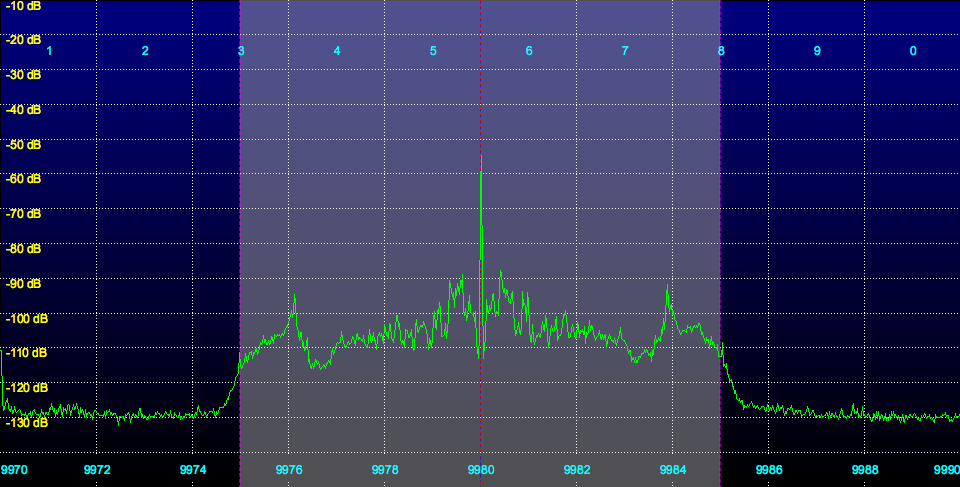
You can see the carrier on 9980 kHz, which consumes most of the transmitter power. Indeed, for a 100% modulated AM transmission, the carrier consumes half of the transmitted power. The carrier power is constant, so for less than 100% modulation (which is typical) the carrier is using more than half of the power. The carrier is necessary for demodulation of the sidebands at the receiver, but conveys no useful information.
To the left and right of the carrier are the lower and upper sidebands. They are symmetrical about the carrier, and convey identical information. Each has the same amount of transmitted power. For the case of 100% modulation, each has one quarter of the total transmitted power. For the typical case of less than 100% modulation, each has less than a quarter.
Next is the spectrum of an SSB signal, USB (Upper Side Band) in this case (click on it to enlarge it):
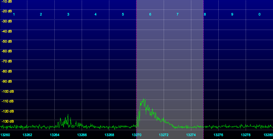
This station is transmitting on 13270 kHz. There is no carrier, and only one sideband is transmitted. Remember that the carrier consumes at least half of the transmitted power, and each sideband uses half of the remaining power, or one quarter for 100% modulation. So in the case of SSB, for 100% modulation, four times the power is available for the sideband as compared to AM, for a given total transmitter power. Four times is equivalent to 12 dB, or two S units.
As you can imagine, this is significant. I’ve created some simulated recordings of USB signals. For these simulations, I assumed that the typical modulation would be about 50%. A 100% modulated signal would sound louder (less noise, better SNR).
Listen to the simulated recordings below to see the effects of various Signal to Noise Ratios:
0 dB Signal to Noise Radio (SNR)
6 dB Signal to Noise Radio (SNR)
10 dB Signal to Noise Radio (SNR)
20 dB Signal to Noise Radio (SNR)
40 dB Signal to Noise Radio (SNR)
It might also be useful to compare them to the previously generated AM signals:
0 dB Signal to Noise Radio (SNR)
6 dB Signal to Noise Radio (SNR)
10 dB Signal to Noise Radio (SNR)
20 dB Signal to Noise Radio (SNR)
40 dB Signal to Noise Radio (SNR)
An AM signal with a SNR of 0 dB is almost impossible to listen to, while an SSB signal, while difficult, is intelligible.
These results suggest that homebrew 10 watt SSB transmitters would produce signals that could quite easily be received by listeners, in cases where an AM transmitter of the same power level would produce a weak signal with an SNR too low to be readily received. The problem, of course, is that SSB transmitters are much more difficult to construct. Ham transceivers are of course quite easy to obtain, and used ones are often relatively inexpensive (although not as cheap as the $30 or so it costs to build a grenade type transmitter).
Many operators run their SSB transmitters at full power, but it is possible that they would reach many of their listeners with lower power, possibly reducing the risk of FCC enforcement actions, if they are indeed related to power levels.
On a related note – why refer to SSB as “Satan Side Band”? While SSB is a far more efficient transmission method than AM, it does have one drawback. With an AM signal, being “on frequency” is not important. The transmitter and receiver frequencies can be off by hundreds of hertz, with virtually no impact on the received signal. The carrier is used in the demodulation (reconstruction of audio) of the signal by the receiver. As long as the carrier and sidebands fit within the receiver’s passband, the signal will be correctly demodulated.
This is not true with SSB. With SSB, there is no transmitted carrer. The receiver must produce it’s own carrier (often referred to as the BFO or Beat Frequency Oscillator in older radios). Ideally, the BFO frequency is exactly on the frequency of the missing carrier from the transmitted signal. In practice, there will always be an offset, due to neither radio being exactly on frequency. This offset is directly translated into an offset for all demodulated audio.
For example, if the radios are off frequency by 100 Hz, then all of the demodulated audio will be shifted by 100 Hz. For voice communications, this is not a serious problem. The speech can still be understood, and it is usually quite easy for the listener to adjust the received frequency until the audio “sounds right”.
The problem is with music. Here, even small tuning errors of ten Hz can cause the audio to “not sound right”. If you know the song in question well enough, you can adjust the received frequency until this error is reduced enough. There are two potential remaining problems, however:
First, many digitally tuned radios cannot tune with infinite resolution, or even in 1 Hz steps. Rather, they may be limited to a 10 Hz tuning step. 10 Hz is still too much of an error for listening to music. Some radios get around this by having a knob that can be turned to adjust the BFO in an analog fashion (often called fine tuning, etc).
The second problem is drift. If the transmitter is drifting around (or the receiver, or both), then the tuning knob will need to be continuously adjusted to bring the station back on frequency.
While I’ve always preferred AM over SSB due to the audio quality, there’s no doubt that watt for watt, SSB results in a much better SNR for the listener.