SSTV (Slow Scan TV) Images Received From The ISS (International Space Station)

The International Space Station is sending SSTV (Slow Scan TV) images on 145.8 MHz today through Friday. Here are two images I just copied from the 1938 UTC (2:48 PM EST) pass.

They were transmitted in PD120 mode, and copied using MultiMode Cocoa software (which I happened to write), on a netSDR receiver connected to a discone antenna (which is many years old, and missing several elements).

SSTV is a method of transmitting a picture using audio tones. It takes about two minutes to send an image. Hence the Slow part of Slow Scan TV.

What does SSTV sound like? Here’s a recording of the audio that produced the second image: http://radiohobbyist.org/blog/mypics/iss_sstv.mp3

Construction of a Helical Antenna for SATCOM Listening

Previously I wrote about the various kinds of transmissions you can heard on the 250 MHz SATCOM satellites. While you can pick these up with a standard scanner antenna, reception is much better with a directional antenna.

This page documents my project to construct a helical antenna for SATCOM listening, 240-270 MHz.

The antenna is based off the design found on this page, which has the specific dimensions and other technical details.

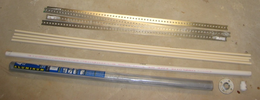
Here are the supplies:
Four 4 ft long strips of steel, four 5 ft long pieces of 1/2″ PVC pipe, one 5 ft long piece of 1 1/4″ PVC pipe for the boom, and window screening for the ground plane.

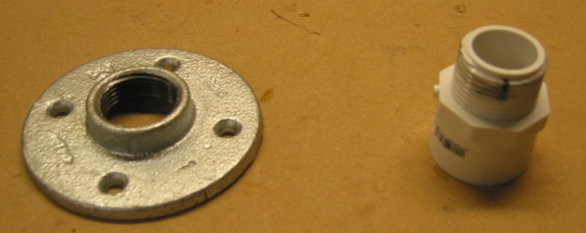
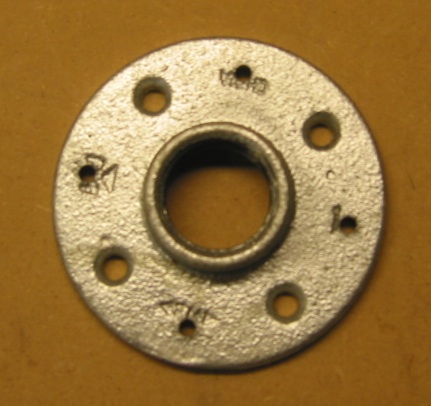
Here’s a close up of the flange and fitting for the PVC boom:

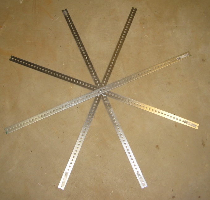
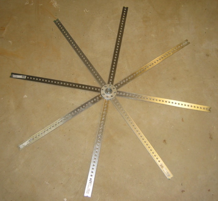
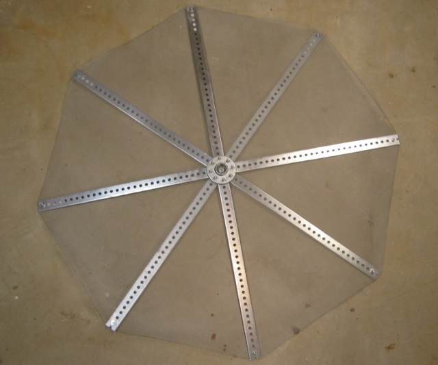
Here are the four steel strips arranged in the radial pattern:

Next I drilled four additional holes in the flange, so it could be screwed to the eight radials:

#10 hardware was used to attach it:

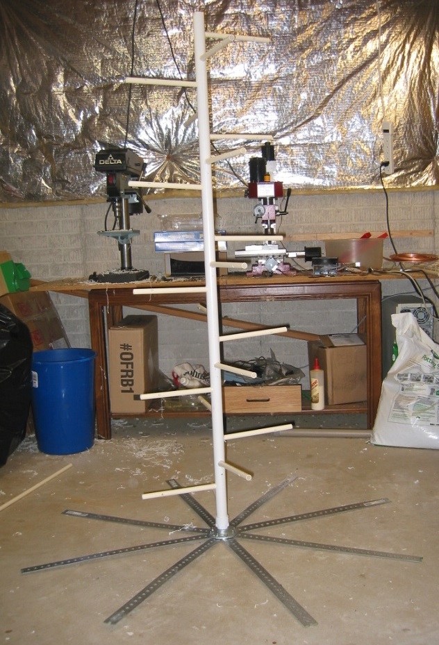
Here it is with the PVC boom attached, to see the overall size:

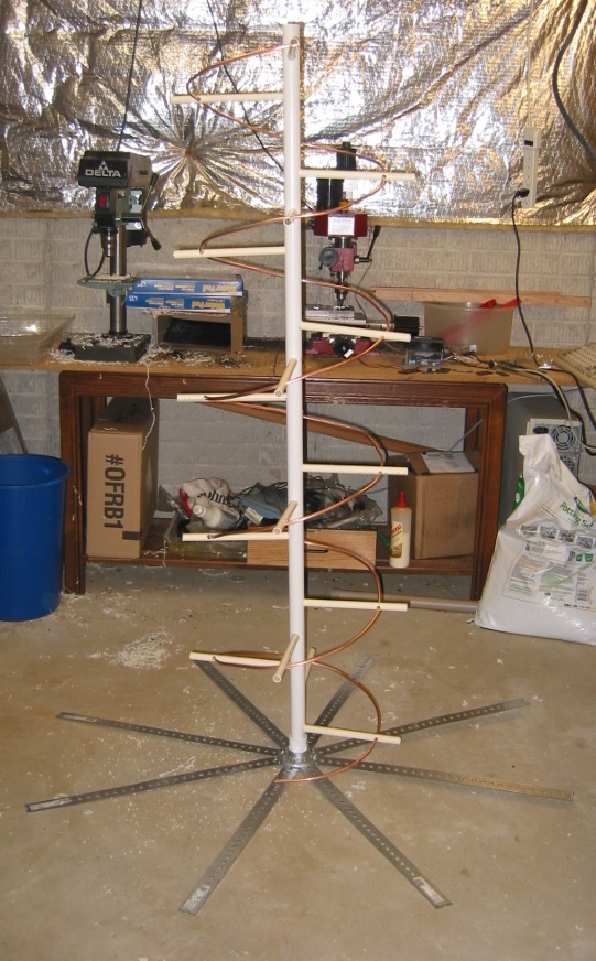
And now with the 20 supports for the tubing installed:

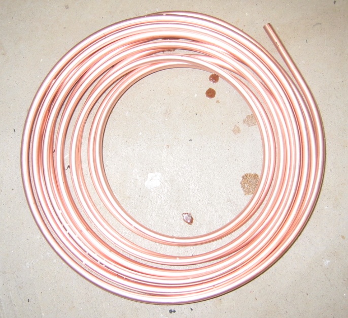
The tubing is 1/4 inch diameter:

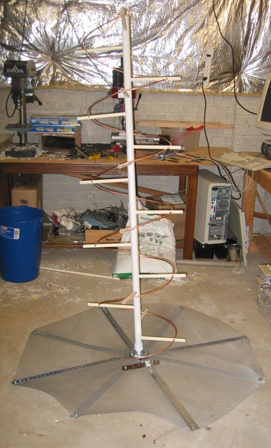
Here it is with the 5 turns of 1/4″ diameter tubing:

The screening has been added to the reflector. It is sandwiched between the strips for support:

The [mostly] assembled helical antenna. The matching section is made from tin-plate and is cut to be a quarter of a turn, about 60mm wide. It’s soldered or bolted to the ground plane at the connector end, and supported by an adjustment screw at the other end. I’ve honestly not noticed much if any difference in the received signal, by fiddling with it. See http://www.uhf-satcom.com/uhf/uhfantenna.html for more details on the matching section.

Final assembly will be done outside, so everything is not tightly fastened yet:

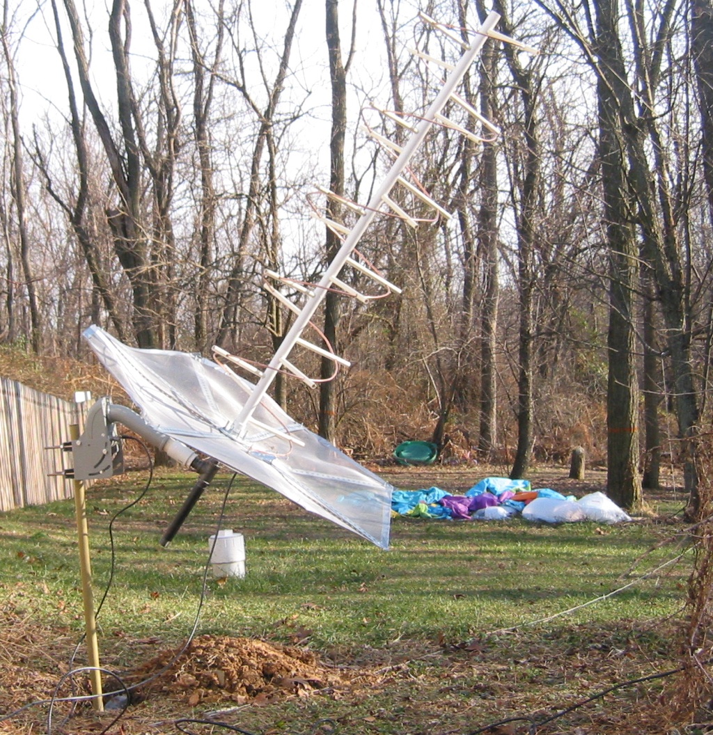
Here it is outside, mounted on a SG-9120 motor. The motor uses the DiSEqC protocol for control, which is sent over standard coax cable. It is a standard in the satellite TV industry.

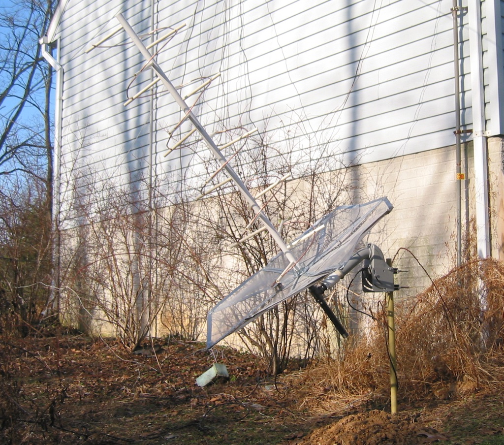
The motor is controlled by a Moteck digibox, which sits inside the shack:

Another view:

The angle of the motor is adjusted based on the latitude of the receiving site, so that as the motor turns the satellite tracks across the geostationary orbit.

UHF Pirates – 250 MHz SATCOM Monitoring

UHF SATCOM refers to satellite repeaters that operate between 240 MHz and 270 MHz. To receive SATCOM, you need a receiver that can tune the frequency range in narrow FM (most modern scanners can do this). You also need an outside antenna, and possibly a LNA preamp.

The satellites in question are operated by the US military. They are essentially repeaters in geostationary orbit. Because they are open (no access control) they are often used by third parties, most often by people in Brazil. It is very common to hear Portuguese transmissions. One listener, who spent several years living in Brazil, described it as

Portuguese slang spoken by people who never paid attention in school

Back in 2009, 39 Brazilian pirates were busted, but the activity continues.

Here’s a recording of SATCOM pirates, and another recording of SATCOM pirates

255.550 MHz is very heavily used by the Brazilian pirates. As I am typing this, I am also hearing pirates on 253.500, 253.750, and 262.190 MHz.

There is an excellent breakdown of all of the 250 MHz SATCOM Transponders By Satellite

While you can start with a basic outdoor scanner antenna, such as a discone antenna or other scanner antenna, many serious listeners eventually build a directional antenna, such as a helical. I will have construction information about one that I built in a future article.

Next, since the signal levels are often very weak, the use of a LNA preamp is highly recommended. I built one of the Down East Microwave Inc. GaAs pHEMT pre amp kits, and find that it really helps a lot.