Building an RF Noise Generator For Testing Filters

It’s often handy to have an RF noise generator when testing various circuits, especially filters. I was working on a low pass filter for long wave, and wanted a way to measure the performance of the filter.

This is the noise generator I came up with. It’s a fairly simple circuit:

A zener diode as the noise source. Zener diodes, when conducting a very low current, produce a wide spectrum of noise. In this case I used a 6.8 volt zener diode, similar values should work as well.
A single NPN transistor used to amplify the noise form the zener diode.
A variable resistor to adjust the current through the zener diode for maximum noise.
Three resistors, four capacitors, and an inductor (to filter out noise you don’t want, from the power supply).

In my case, I powered the generator from a 12 volt DC power supply, you could use a 9 volt battery as well, if you wish.

Below is the schematic (you can click on any of the images to see them full sized):

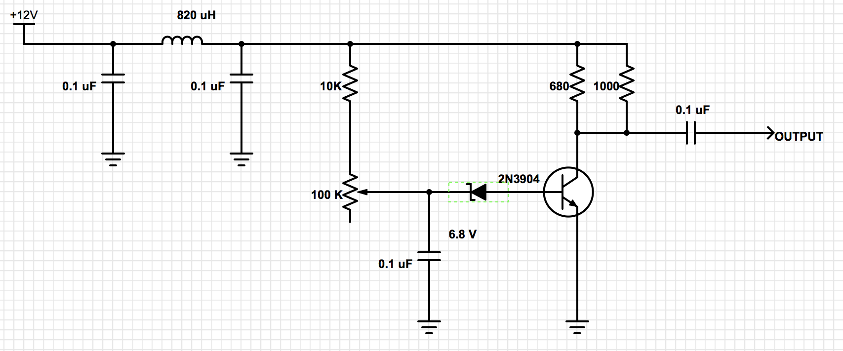
The incoming DC power is filtered by the inductor and two capacitors.

Next it goes through the variable resistor as well as a fixed 10K resistor, so that the maximum current through the zener diode is limited to a safe value during adjustment. The noisy zener diode current is then applied to the base of the transistor, used as a common emitter amplifier. I used a 2N3904, other values should work as well, though you may need to adjust resistor component values. The 0.1 uF capacitor keeps the voltage on the zener diode relative constant.

The 680 and 1000 ohm resistors in parallel are values I had in my parts bin, suitable to use in parallel based on the current to the base of the transistor. The transistor output is the AC coupled through another 0.1 uF capacitor.

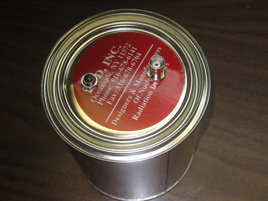
Below is a photograph of the circuit, build on the lid of a 1 pint paint can. I have a number of these from geiger tubes that I purchase for use in radiation detectors that you can plug into your computer for experiments as well as long term measurements and graphing. Hey, want to buy one of my geiger counters? Full details are here: http://www.blackcatsystems.com/GM/GeigerCounters.html

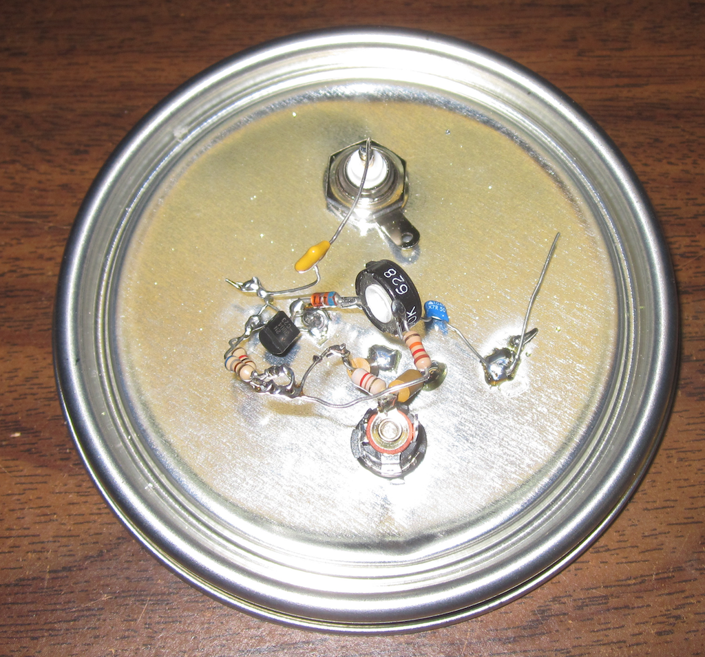
OK, back to the noise generator. The paint can lids are handy for prototyping RF circuits. You can built them dead bug style on the bottom side of the lid, test them out, then put them on the can for your RF shield, as shown below. The two connectors are a BNC jack for the RF output, as well as a standard DC power jack for the power supply.

For looking at the generated noise spectrum, I used the fabulous SdrDx SDR software by Ben, AA7AS, along with an AFE822x SDR.

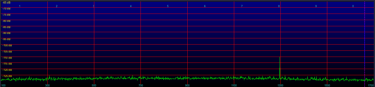
Below is the noise level with the RF noise generator powered off (you can see an RFI noise source around 1300 kHz from elsewhere in my lab, which I have not yet tracked down):

And with it powered on:

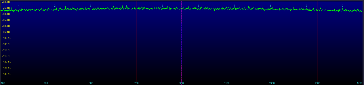
The increase in noise level is about 50 dB, very suitable for testing filters and such.

DXing DGPS Stations with Your Android or iPhone / iPad

Looking for a new set of stations to DX? You might want to consider DGPS stations, heard on the long wave band.

DGPS stations transmit the difference between positions indicated by GPS satellite systems and the known fixed position of the station. This allows higher accuracy. DGPS transmissions are 100 or 200 baud and are transmitted on frequencies from 285 kHz to 325 kHz. Hundreds of these stations are operated by the Coast Guard and other agencies, and they can be interesting DX targets.

A pair of apps allow you to decode these transmissions on your smartphone or tablet. There’s the Android version of DGPS decoder was well as the iPhone/iPad version of DGPS Decoder. It is also available for the Kindle Fire on the Amazon App Store.

I wrote a previous article about how to use MultiMode to decode these transmissions on your Mac.

Here’s screenshots of the two apps in use, you can click on them to enlarge them:

You’ll need a radio that can tune the 285 kHz to 325 kHz range in SSB or CW mode. To decode the transmission, tune your radio to a DGPS frequency. You can either tune directly to the frequency in CW mode, in which case you set the center frequency in this app to frequency of the tone produced by your radio in CW mode, usually close to 800 Hz, or use USB mode, tune 1 kHz low, and set the center frequency in the app to 1000 Hz.

You can listen to an example DGPS audio recording, which you can also use to test out the apps, and practice correctly tuning in the transmissions, before trying for some actual stations on your radio. This example is 200 baud, with a center frequency of 1000 Hz.

A typical decoded message looks like this:

[23:24:00 08/08/16] 806 12 13 289.0 kHz Driver, VA United States 36.9633 -76.5622 306.61 km 172.711 deg

First the current UTC date and time are printed in brackets.
Then the station ID, 806 in this case, as well as the two reference IDs, 12 and 13 in this case.
That is followed by the assigned frequency, 289.0 kHz for this station. You can compare this value to what your radio is tuned to, they should match. If they don’t, then ignore this message, as it was incorrectly received. With weak signals, it is common to receive incorrect messages, because static or other interference has corrupted some of the bits. Just ignore them.
The location of the station is then displayed, the city, state, and country, followed by the station location.
Then the distance and bearing to the station is displayed, providing you have correctly set your location in the app.

Here’s a list of some stations I have previously received here with a modest 200 ft random wire antenna:

286.0 kHz Sandy Hook, NJ United States 40.4747 -74.0197 235.632 km
306.0 kHz Acushnet, MA United States 41.7492 -70.8886 529.571 km
305.0 kHz Dandridge, TN United States 36.0225 -83.3067 723.745 km
311.0 kHz Rock Island IL United States 42.0203 -90.2311 1245.06 km
289.0 kHz Driver, VA United States 36.9633 -76.5622 231.719 km
291.0 kHz Hawk Run, PA United States 40.8889 -78.1889 280.839 km
293.0 kHz Moriches, NY United States 40.7944 -72.7564 340.978 km
294.0 kHz New Bern, NC United States 35.1806 -77.0586 434.825 km
295.0 kHz St Mary's, WV United States 39.4381 -81.1758 448.281 km
297.0 kHz Bobo, MS United States 34.1253 -90.6964 1414.92 km
301.0 kHz Annapolis, MD United States 39.0181 -76.61 52.734 km
303.0 kHz Greensboro, NC United States 36.0694 -79.7381 463.251 km
304.0 kHz Mequon, WI United States 43.2025 -88.0664 1110.64 km
307.0 kHz Hagerstown, MD United States 39.5553 -77.7219 160.52 km
296.0 kHz St Jean Richelieu, QC Canada 45.3244 -73.3172 736.38 km
322.0 kHz St Louis, MO United States 38.6189 -89.7644 1190.3 km
292.0 kHz Cheboygan, MI United States 45.6556 -84.475 1013.8 km
314.0 kHz Card Sound, FL United States 25.4417 -80.4525 1560.45 km
288.0 kHz Cape Ray, NL Canada 47.6356 -59.2408 1650.3 km
290.0 kHz Louisville, KY United States 38.0175 -85.31 816.337 km
292.0 kHz Kensington, SC United States 33.4906 -79.3494 681.801 km
313.0 kHz Moise, QC Canada 50.2025 -66.1194 1464.05 km
302.0 kHz Point Loma, CA United States 32.6769 -117.25 3697.45 km