Setting up OP25 Scanner Trunking on an Ubuntu Virtual Machine

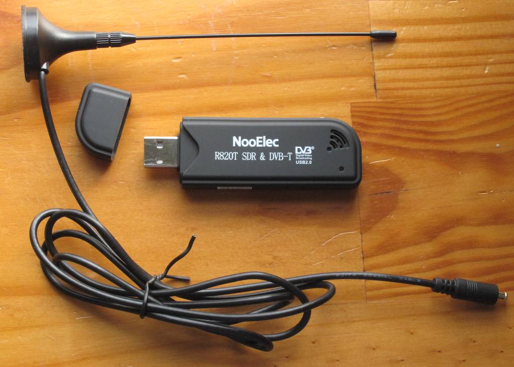
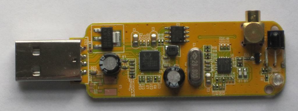
After a multi day (week?) saga of trying to get op25 to run on a Raspberry Pi, I decided to give it a try on a linux virtual machine, and had much better results. For the radio hardware I used one of the ubiquitous RTL SDR Dongles.

https://www.amazon.com/gp/product/B0129EBDS2/ref=ox_sc_act_title_1?tag=blackcatsyste-20

I used this guide as a reference / starting point: https://www.hagensieker.com/wordpress/2018/07/17/op25-for-dummies/

Here’s what I did to get things running:

I’m using VirtualBox for the VM setup. I did it on macOS, it should work the same way under Windows.

Create a new linux VM. I gave it 8G of RAM (perhaps overkill) and a 30G volume.

Download the Ububtu installation ISO: https://www.ubuntu.com/download/desktop

Go to Settings -> Storage for the new VM, select the ISO as the optical disc image.

Boot the VM, and install. I won’t go into the installation details, in general I found the defaults worked fine.

I installed the Guest Additions so I could cut and paste between the OS and VM.

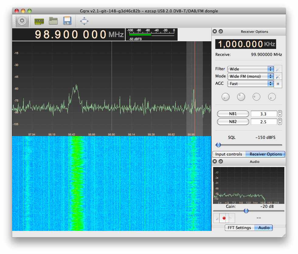
Next I installed gqrx so I could check out that the RTL Dongle was working. The stock Ububtu I installed did not come with it:

sudo apt install gqrx-sdr

I plugged in the RTL Dongle, went to Devices -> USB in the VM menu, and assigned the dongle to the VM for use. (Don’t forget this step!)

I ran gqrx, and verified the dongle was working.
gqrx

Next, before installing op25, I had to install git:

sudo apt install git

Then grab op25:

git clone https://github.com/boatbod/op25.git

Switch to the op25 directory that was just created:

cd op25

And install it:

./install.sh

Then install gnuplot so you can see the spectrum and constellation plots:

sudo apt-get install gnuplot-x11

Go to the apps directory for op25:

cd op25/gr-op25_repeater/apps

Next you need to go to https://www.radioreference.com/ and locate the details on the trunking system for your area. Several control frequencies may be listed for your system, you need to find the currently active one. In my case, I checked them all until I found one frequency that was continuously transmitting, 852.9375 MHz.

Now, the next part was perhaps the most difficult, you need to determine the correct ppm error for your RTL dongle. All dongles seem to be off, some more than others. Mine turned out to be off by a LOT. The other tutorials I read gave examples with ppm errors of around 2 or 3. I spent a lot of time trying small values like that, and even up to 20 or 30, without success.

I brought up the spectrum plot in op25 (hit the 1 key) and looked at the spikes, representing transmissions, and checked them against my R-7000 receiver. It was confusing at first, trying to match things up. I eventually realized my dongle was off by a huge factor – about 150 kHz at 853 MHz. I ended up using a ppm value of 173, and that seems to be working. Your value will likely be different, but carefully use the spectrum plot to determine what it is, or at least get close. Then you can iterate up and down by 1 ppm. Another recommendation I read, and used, was to set the offset (used to avoid the 0 Hz spike) to zero for initial testing.

Here’s the command to run op25 with a control frequency of 852.9375 MHz, ppm of 172, and an offset of 0 Hz:

./rx.py –args ‘rtl’ -N ‘LNA:47’ -S 2400000 -f 852.9375e6 -o 0 -q 172

I found I still need to use the , and . keys to shift the received frequency offset around until the program started to decode data correctly (the tsbks value will start incrementing). Again I used the spectrum plot to
help center the control frequency.

When properly tuned, the constellation plot looks like this, hit the 2 key to bring it up:

Once that worked, the next step was to find the NAC value, which is displayed in the op25 program, in my case it was 0x661.

In the apps directory, open the trunk.tsv file in the LibreOffice editor built into Ubuntu, it opens as a spreadsheet. I edited it as follows, entering in a system name, setting the control channel and NAC values. I left the modulation alone (CQPSK) and entered a new tags file name, we’ll create that file next.

I then duplicated the tompkins.tsv file, renamed the duplicate carroll.csv to match what I entered in trunk.tsv, and then opened it in LibreOffice.

It’s a bit tedious, but you have to enter in each talkgroup tag number and name. I just went down the list of talkgroups in radio reference, and it took a few minutes. Part of the list:

Once that was done, I ran op25 again. You can append 2> followed by a filename, to route error messages to a file, so they do not clutter the screen:

./rx.py --args 'rtl' -N 'LNA:47' -S 2400000 -o 25000 -q 181 -T trunk.tsv -V -2 -U 2> stderr.2

I am using an offset of 25 kHz (25000 Hz), and notice I now had to change the ppm to -181, the RTL dongle drifted that much in a few hours!

Update, I also got it working with the AirSpy, which turned out to be very easy. I just had to install the AirSpy support with:

sudo apt install airspy

Running it is as easy as:

./rx.py --args "airspy" -q 3 -N 'IF:12,MIX:12,LNA:12' -S 2500000 -V -2 -U -T trunk.tsv

As you can see, the AirSpy is much more accurate, the ppm value is only 3.

I still need to optimize the gain settings, but this is working nicely. Much better reception than the RTL dongle, as you can imagine. Hmm… unfortunately, op25 is freezing after a while with the AirSpy. Need to investigate this…

Another update:

I decided to install Ububtu on an older i3 laptop. I resized the Windows 10 drive, and freed up 200GB (perhaps excessive, but the drive is 750GB, and I don’t really use the laptop much anymore for Windows) for the linux partition.

I followed the above steps and got gqrx running first, then op25. I have not tried with the AirSpy yet, but even with the RTL dongle, things are improved, the audio quality and overall reception are noticeably better.

Decoding ADS-B Aircraft Transponders: An SDR for $17 – The R820T USB RTL-SDR DVB-T Dongle – Part 3

Please be sure to read Part 1 and Part 2, if you’re new to this series of articles.

All aircraft contain a piece of avionics technology called a transponder. This contains a receiver, and a transmitter. When the signal from ground radar is received, the transponder transmits a short burst on 1090 MHz, encoded with information.

There are several possible replies from an aircraft transponder:

  • Mode A replies with a target ID code
  • Mode B replies with the barometric altitude of the plane
  • Mode S, also called the Extended Squitter, is the one we’re interested in.

Mode S, also called ADS-B allows a variety of types of data to be sent from the transponder, including:

  • ICAO aircraft code (the tail number of the plane can be obtained from this)
  • Flight Number
  • Altitude
  • Location (Longitude and Latitude)
  • Heading

There’s an online document called ADS-B for Dummies that goes through the various messages, and their format.

Since the RTL dongles can receive 1090 MHz at a wide bandwidth, it turns out to be possible to use them as low cost transponder decoders. Very low cost. You can pick them up for around $15 on eBay. Dedicated ADS-B receiver packages are more. Much more. As in hundreds of dollars.

There are quite a few packages out for the RTL dongles that decode ADS-B transmissions. For Windows, there’s ADSB#:

For linux and Mac OS X, there’s Dump1090

I compiled Dump1090 for Mac OS X, here is what the output looks like:

The columns across the screen:

  • Hex – the ICAO code for the plane
  • Flight – flight number
  • Altitude – altitude in feet
  • Speed – speed in mph
  • Lat – latitude of position
  • Lon – longitude of position
  • Track – heading in degrees
  • Messages – the number of messages from this plane that have been received
  • Seen – how long ago (in seconds) since the last message from the plane, that is, how long since it has been last seen (or heard from)

I’ve since ported the Dump1090 code over to Cocoa on Mac OS X, resulting in Cocoa1090:

Cocoa1090 uses the ICAO hex code to derive the tail number (and aircraft model) from a database in a text file, which are also displayed.

A beta version of Cocoa1090 can be downloaded here: http://www.blackcatsystems.com/software/cocoa1090.html

Spying on your neighbor’s grill thermometer – Monitoring the 433.92 MHz ISM Band with an RTL Dongle

Remote weather stations, some car key fobs (although many in the US use 315 MHz), wireless grill thermometers, and many other devices use the 433.92 MHz ISM (Industrial, Scientific and Medical) band. Chances are good that if it is a wireless sensor, it uses this band.

Here is a waterfall showing transmissions observed here, using one of the inexpensive USB RTL DVB-TV Dongles:

The entire waterfall occupies 139 seconds.

You can observe several periodic transmissions. I have a remote weather station and a remote thermometer, so that accounts for two of them.

If you have an RTL tuner dongle, take a look and see what 433 MHz transmissions are occurring near you.

An SDR for $17 – The R820T USB RTL-SDR DVB-T Dongle – Part 2

   PSK31     
   iPad app to decode PSK31     

Earlier, I wrote about the RTL2832U based USB TV tuner dongles that can be turned in an inexpensive Software Defined Radio (SDR). Please take a moment to read that for an overview of these insanely great (for the price) modules, if they’re new to you. I’ve since mounted the dongle in a small metal enclosure:

There were two reasons for this, first to reduce noise pickup, the second was to easily add an F style antenna connector.

Next, I wanted to try getting the rtl-sdr series of command line programs to run. I had tried a set of pre built binaries, but they didn’t work, so I decided to build it myself.

First I got the code from http://cgit.osmocom.org/cgit/rtl-sdr/

I followed the instructions from http://sdr.osmocom.org/trac/wiki/rtl-sdr
cd rtl-sdr/
autoreconf -i
./configure
make
sudo make install
sudo ldconfig

The first problem was after ./configure, namely:
configure: error: Package requirements (libusb-1.0 >= 1.0) were not met:

Turns out I had an ancient version of libusb.
sudo port install libusb
solved that.

With the programs built, the next step was running rtl_test:
$ rtl_test -t
Found 1 device(s):
0: ezcap USB 2.0 DVB-T/DAB/FM dongle

Using device 0: ezcap USB 2.0 DVB-T/DAB/FM dongle
Found Rafael Micro R820T tuner
Supported gain values (29): 0.0 0.9 1.4 2.7 3.7 7.7 8.7 12.5 14.4 15.7 16.6 19.7 20.7 22.9 25.4 28.0 29.7 32.8 33.8 36.4 37.2 38.6 40.2 42.1 43.4 43.9 44.5 48.0 49.6
No E4000 tuner found, aborting.

So far so good.

Next I tried running rtl_fm, which lets you demodulate a FM signal. AM is supposedly also supported. I say supposedly because I could not get rtl_fm to work properly. It would run, and write demodulated sound data to a file, but playing it back always produced gibberish. Also, the files were way too large for the specified sample rate and length of time the program was running. The documentation for rtl_fm is sketchy, even by open sores standards. For example, the list of options includes:
[-s sample_rate (default: 24k)]

which naturally makes you suspect -s sets the sample rate. It does no such thing, it actually sets the IF bandwidth. Again, supposedly.

After several hours of trying to get rtl_fm to work properly, I threw in the towel, and moved on to rtl_tcp, which acts as a little TCP server, sending I/Q data to a connected client. I had much better luck here. Running the program produced the following:
$ ./rtl_tcp
Found 1 device(s).
Found Rafael Micro R820T tuner
Using ezcap USB 2.0 DVB-T/DAB/FM dongle
Tuned to 100000000 Hz.
listening...
Use the device argument 'rtl_tcp=127.0.0.1:1234' in OsmoSDR (gr-osmosdr) source
to receive samples in GRC and control rtl_tcp parameters (frequency, gain, ...).

I then connected to it via telnet in another console window:
$ telnet 127.0.0 1234

And the rtl_tcp server program responded with:
client accepted!
and proceeded to send I/Q data to my telnet session, which spewed it to the window. Mission accomplished.

Next I wrote a small program to open a connection to the rtl_tcp server, and grab all the received data, count the number of bytes per second, and display it once per second, as a quick and dirty test to see if everything was working OK. I got around 4M bytes per second, which is correctly for a 2 MHz sample rate (the data is 8 bit I/Q, so there are two bytes per sample).

Having accomplished this, the next step was to make some use of the data. I thought trying to decode and display ADS-B aircraft transponder messages on 1090 MHz would be fun. That is my next post.

An SDR for $17 – The R820T USB RTL-SDR DVB-T Dongle

You may have heard of the latest SDR craze to hit the radio hobby – the RTL based USB dongle TV tuners. These were originally made to receive and decode the European standard digital television broadcasts. An enterprising hobbyist discovered that they can be tuned throughout the VHF and UHF range, and that you can get at the raw sampled data from the onboard A/D converter (only 8 bit, however). This allows them to be used as a very inexpensive Software Defined Radio (SDR) for VHF and UHF. How inexpensive? Mine was $17 shipped, although you can find them for even less, if you’re willing to get them direct from China and wait a few weeks for delivery.

Here is what I got:

There’s the dongle itself, as well as the small (about 4″) antenna.

It’s interested to note that the enclosure actually says SDR on it, the word has apparently gotten out about the SDR applications for this dongle, and someone is private branding them.

Here’s what the inside looks like:

The USB connector is on the left, the MCX style RF connector is on the upper right.

There are control programs available for Windows, Mac OS X, and Linux. For software, first I decided to try rtl-sdr I copied the libraries to the specified locations, restarted, and was greeted with:

>:rtlsdr_osx cps$ rtl_test -t
Found 1 device(s):
0: ezcap USB 2.0 DVB-T/DAB/FM dongle

Using device 0: ezcap USB 2.0 DVB-T/DAB/FM dongle
Failed to open rtlsdr device #0.

It’s possible this is an older version of the rtl-sdr package, that expects the E4000 tuner chip. (Although a less cryptic error message would sure be helpful)

Then I tried Cocoa Radio. It crashes on launch. So far open sores is zero for two.

So next I tried the Mac OS X port of gqrx. Much better! It came right up, and within a minute I was receiving FM broadcast stations. I have noticed that if I make a change to the sample rate, I need to quit and re-start the app before putting it into run mode, or it crashes.

The sensitivity is not bad, I was able to pick up stations about 50 or 60 miles away using the included tiny 4″ antenna, laying on my desk.

Below is a screenshot of gqrx running on the FM band, you can see three FM broadcast stations, at 97.9, 98.5 and 99.1 MHz, the latter is tuned in for demodulation.:

I was also able to pick up 2m packet radio transmissions on 144.39 MHz, and one of the NOAA weather radio stations, on 162.525 MHz.

There are many varieties of these TV tuner dongles out there, mostly the difference is the RF tuner chip used. Previously the E4000 tuner was the preferred one for SDR applications, as it had the widest tuning range, although with a gap in the middle. It apparently is no longer made and is difficult to find tuners that use it. Currently the R820T tuner chip seems to be the preferred one for SDR use, the tuning range is slightly less, but there is no gap. Some eBay vendors identify the chip used, many do not, but there are lists online of the various USB dongles by brand name and model number, with the tuner chip specified, such as here.

My next project was mounting the dongle in a small metal enclosure, with a different RF connector, so I can easily connect one of my existing outdoor antennas to it. Read all about it here.

Construction of a Helical Antenna for SATCOM Listening

Previously I wrote about the various kinds of transmissions you can heard on the 250 MHz SATCOM satellites. While you can pick these up with a standard scanner antenna, reception is much better with a directional antenna.

This page documents my project to construct a helical antenna for SATCOM listening, 240-270 MHz.

The antenna is based off the design found on this page, which has the specific dimensions and other technical details.

Here are the supplies:
Four 4 ft long strips of steel, four 5 ft long pieces of 1/2″ PVC pipe, one 5 ft long piece of 1 1/4″ PVC pipe for the boom, and window screening for the ground plane.

Here’s a close up of the flange and fitting for the PVC boom:

Here are the four steel strips arranged in the radial pattern:

Next I drilled four additional holes in the flange, so it could be screwed to the eight radials:

#10 hardware was used to attach it:

Here it is with the PVC boom attached, to see the overall size:

And now with the 20 supports for the tubing installed:

The tubing is 1/4 inch diameter:

Here it is with the 5 turns of 1/4″ diameter tubing:

The screening has been added to the reflector. It is sandwiched between the strips for support:

The [mostly] assembled helical antenna. The matching section is made from tin-plate and is cut to be a quarter of a turn, about 60mm wide. It’s soldered or bolted to the ground plane at the connector end, and supported by an adjustment screw at the other end. I’ve honestly not noticed much if any difference in the received signal, by fiddling with it. See http://www.uhf-satcom.com/uhf/uhfantenna.html for more details on the matching section.

Final assembly will be done outside, so everything is not tightly fastened yet:

Here it is outside, mounted on a SG-9120 motor. The motor uses the DiSEqC protocol for control, which is sent over standard coax cable. It is a standard in the satellite TV industry.

The motor is controlled by a Moteck digibox, which sits inside the shack:

Another view:

The angle of the motor is adjusted based on the latitude of the receiving site, so that as the motor turns the satellite tracks across the geostationary orbit.

UHF Pirates – 250 MHz SATCOM Monitoring

UHF SATCOM refers to satellite repeaters that operate between 240 MHz and 270 MHz. To receive SATCOM, you need a receiver that can tune the frequency range in narrow FM (most modern scanners can do this). You also need an outside antenna, and possibly a LNA preamp.

The satellites in question are operated by the US military. They are essentially repeaters in geostationary orbit. Because they are open (no access control) they are often used by third parties, most often by people in Brazil. It is very common to hear Portuguese transmissions. One listener, who spent several years living in Brazil, described it as

Portuguese slang spoken by people who never paid attention in school

Back in 2009, 39 Brazilian pirates were busted, but the activity continues.

Here’s a recording of SATCOM pirates, and another recording of SATCOM pirates

255.550 MHz is very heavily used by the Brazilian pirates. As I am typing this, I am also hearing pirates on 253.500, 253.750, and 262.190 MHz.

There is an excellent breakdown of all of the 250 MHz SATCOM Transponders By Satellite

While you can start with a basic outdoor scanner antenna, such as a discone antenna or other scanner antenna, many serious listeners eventually build a directional antenna, such as a helical. I will have construction information about one that I built in a future article.

Next, since the signal levels are often very weak, the use of a LNA preamp is highly recommended. I built one of the Down East Microwave Inc. GaAs pHEMT pre amp kits, and find that it really helps a lot.