Ferrite Core 1, RFI 0

Once again, a giant ferrite toroid coil saves the day. I have a random wire antenna (about 100 foot long) running into the basement workshop, fed with RG-6 coax (the coax shield is left floating at the antenna end). Reception was horrible, I could barely hear anything, even SWBC stations. I considered that maybe it wasn’t a lack of signal problem so much a signal to noise problem, so I located a large ferrite toroid coil from the junkbox, wrapped as many turns of coax around it as I could (about a dozen), and placed that in series with the incoming coax, just before the radio. Voila, the noise/hash was gone. The choke helps to reduce RFI flowing as currents on the shield of the coax.

The ferrite core was a Fair-Rite 5943003801, 61 mm toroid, type 43 ferrite. I buy mine from Mouser for about $4 each: http://www.mouser.com/ProductDetail/Fair-Rite/5943003801

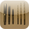
Here’s a photo showing how the coax is wrapped around the toroid core:

And here are some before and after video recordings. The gap about half way through each is when I disconnected the incoming coax to the radio, and inserted the choke, and then reconnected the coax:

More adventures in filtering the power supply for an AFE-822 SDR

I frequency monitor and record the 285-325 kHz DGPS band, looking for DX beacons. Recently, I noticed a noise source centered around 315 kHz, almost 10 kHz wide, on my AFE 822 SDR with a 500 ft beverage antenna:

I tried hunting around the house with a portable radio, looking for it, but could never find it. I then checked on my netSDR, with a 670 ft sky loop antenna, and it was not visible there. Very curious. I then tried the beverage antenna, and could still not observe it. But it was there with the AFE822, with either antenna. This made me suspect noise was entering the AFE-822 through the power supply. I was use the USB input for power, and previously wrote about my attempts to reduce the noise from the power supply. This noise source was new since then, possible due to something else added to the shack.

I decided to put together a filtered DC power supply, using linear wall transformer, and adding filtering via capacitors and an inductor.

The circuit itself is fairly simple:

The output of the transformer I used is about 10 volts under load. I chose a 5 ohm power resistor to place in series, which dropped 2.5 volts, so the resulting DC power supplied to the AFE 822 is 7.5 volts. The value of this resistor depends on the output voltage from the DC supply. The AFE-822 draws 0.5 amps, Ohms Law can be used to calculate the desired resistance. The AFE822 has a voltage regulator inside it (it appears to be an LM7805 variant, possibly low drop out), so it can tolerate a wide range, the AFE 822 website specifies 7 to 10 volts.

The inductor is from the junk box, I don’t know what the value is. While I’m telling myself it helps to filter, I might try to find a known, larger value. The 1000 uF electrolytic capacitors provide low frequency filtering, the 0.047 uF ceramic caps provide RF filtering.

The filter circuit was constructed dead bug style on the lid of a small metal can:

Here it is mounted on the can:

And now the spectrum, with the new power supply. Certainly an improvement: