The Sky Loop Antenna

My present workhorse antenna is a sky loop antenna with a 635 feet perimeter. What exactly is a sky loop antenna? The traditional definition from ham radio circles is that it is a full wave loop antenna, oriented in the horizontal plane. They are often used on 160 and 80 meters. The length or perimeter of a full wave loop antenna is 1005 feet divided by the frequency in MHz. So for 160 meters, say 1.9 MHz, it would be 1005 / 1.9 = 529 ft. The exact size of the loop may be important if you’re transmitting and want a reasonable SWR. For receiving only, it is not as critical, and the “bigger is better” rule usually applies. I ended up with 635 feet because that is the largest length I could easily install.

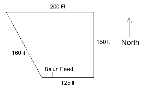
Here is a diagram showing the dimensions and orientation of the antenna:

Reversing the formula to 1005 / length gives you the resonant frequency, 1.58 MHz in my case, which is the top end of the MW band. From my experience, the antenna works great for the upper end of MW, especially the extended band (1610-1700), adequate for the middle of the MW band, and it produces very weak signals at the lower end of the MW band. I’ve yet to hear any transatlantic longwave stations with it.

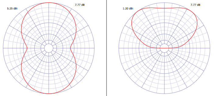
The gain of a loop antenna is proportional to the area. While I don’t have enough space to substantially increase the perimeter of the antenna, I could add perhaps 200 feet at the most. An additional 200 feet would drop the resonant frequency to 1.2 MHz, but I’d substantially increase the area, so it may be a worthwhile project.

The height of the antenna varies dramatically, with some points barely 15 ft above the ground, others are around 40 ft. Again, this was what I could easily achieve. Raising sections of the antenna is a planned Spring project, it will be interesting to see what the improvement, if any, is.

The antenna is constructed from #16 insulated stranded wire, and is suspected from trees around the yard. The feedpoint is a 16:1 balun, and 100 feet of 75 ohm RG-6 coax runs from the balun to the shack. I’ve become a big fan of RG-6 coax for my antenna projects. This is the coax used for TV purposes. It’s available everywhere, and is incredibly cheap and low loss. Yes, it is 75 ohm, not 52 ohm, but for receive only antenna like this, who cares?

Running a NEC simulation, the free space resonant frequency is 1.59 MHz, with an input impedance of 140 ohms, which seems reasonable for a loop antenna. Over an average ground, this shifts to 1.55 MHz and 49 ohms, and over a good ground, 1.55 MHz and 27 ohms. Using an average ground, and running NEC simulations for other frequencies gives the following results:

MHz	R	X	Z
1	35	-2421	2421
2	245	1735	1752
3	83	-181	199
4	941	-3196	3331
5	398	1082	1152
6	203	-354	408
7	2233	-1832	2888
8	507	768	920
9	346	-519	623
10	2392	-489	2441
11	542	437	696
12	447	-609	755
13	2113	845	2275
14	487	250	547
15	771	-650	1008
16	1564	786	1750
17	344	157	378
18	1029	-877	1352
19	1132	797	1384
20	470	47	472
21	1338	-998	1669
22	886	708	1134
23	410	-76	416
24	1497	-509	1581
25	748	664	1000
26	480	-173	510
27	1619	-194	1630
28	675	516	849
29	485	-239	540
30	1815	341	1846

R is the real component of the impedance, X is the reactive, and Z is the overall impedance, all values in ohms. As you can see, the impedance values are all over the place. Looking at them in closer detail would show even finer scale variations, but I’m not sure it would be too useful, as this is a simulation, an estimate of the antenna performance, these are not necessarily the impedance values of the actual antenna. Lies, damned lines, and antenna models.

The large Z impedance values over the HF range are why I went with a 16:1 balun, to better match them to the 75 ohm coax. The downside is that the loop impedance over MW is much lower, and the 16:1 balun probably produces a poor match. A 1:1 balun might be best for MW use, but I’m not sure what would happen at HF, I assume a poorer match and weaker signals. I spend most of my time on HF, anyway.

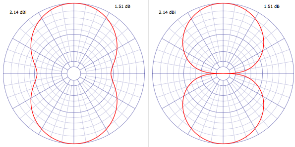
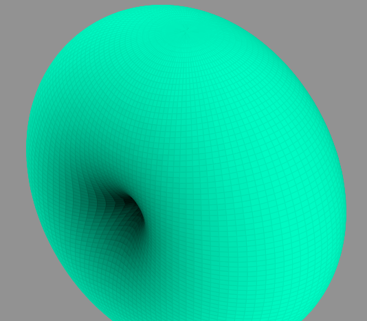
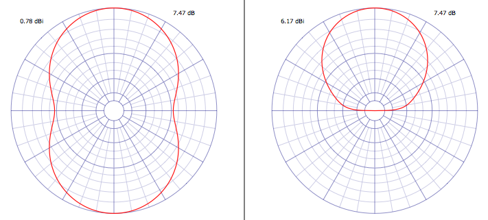
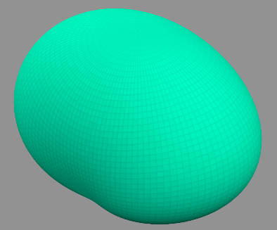
Below is a plot showing the gain of the antenna at three different elevation angles, 30 degrees (low angle radiation, ideal for DX), 60 degrees, and 90 degrees (which would be straight up) for a frequency of 6.9 MHz.

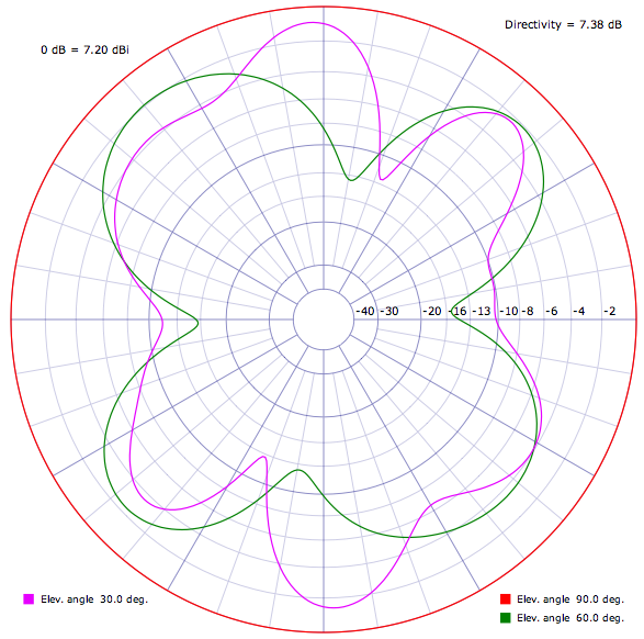
The red circle is the gain for 90 degrees, straight up. This angle for NVIS, where the radio waves are going virtually straight up from the transmitter, and being reflected straight down back to the Earth. The gain is 7.2 dB over an isotropic antenna (an antenna with no gain in any direction). For this case, the antenna has no favored direction, it is equally sensitive in all directions around the compass. For the lower angles, the antenna does have more gain in certain directions, and of course less in others. I find that for NVIS reception of pirates this antenna is excellent, so here’s one case of an antenna model actually approaching reality. DX reception is not bad either, I regularly pick up Europirates, and of course SWBC stations from all over.

One thing I like about the antenna is that it works reasonable well over all of HF and much of MW. I used to have dedicated dipoles for the various HF bands, but it was always a pain to switch antennas when tuning to a different band. And being a loop antenna, the noise levels are much lower than dipoles. I do wish the performance on the lower part of MW was better. I will try enlarging the antenna and see if that improves MW reception.

Don’t let the large size of my build of this antenna discourage you from building your own, if you don’t have the room for one of this size. A full wave loop antenna for 6.9 MHz is 146 feet – that’s a square 36 1/2 feet on a side. Such an antenna should work well from 43 meters on up.

Analyzing Half Wave Dipole Antennas

There are two characteristics that we’re particularly interested in:

First, the radiation pattern. This describes how well the antenna receives (or transmits) a signal in various directions. Below is the radiation pattern for the standard half wave dipole in “free space”, that is, without a ground below it. You can imagine it is in outer space, or so far above the Earth’s surface that there are no effects from the ground.

free space dipole radiation pattern

The antenna wire is oriented east/west. The image on the left is the horizontal pattern. Imagine you’re above the antenna, looking down. This is the pattern around the antenna, all 360 degrees of the compass. There are two main lobes, one to the north, and one to the south. This means that the antenna is particularly sensitive to signals to the north and south, and less so to signals to the east and west. For a transmitting antenna, most of the radiated signal is directed the same way. One rule for antennas is that the radiation patterns are the same for both transmitting and receiving.

The image on the right is the vertical pattern. Imagine you’re at the same height as the antenna, looking at it. The top of the graph represents the signal strength going up, the bottom going down, etc. In this case, there are two sharp nulls directly to the left and right of the antenna. These are in line with the antenna. What this is telling us is that most of the RF energy is directed around the line containing the antenna wire. Here is what it looks like in 3D:
free space dipole radiation pattern 3D

Now let’s make the antenna more realistic by putting it above the ground. In this case, we’re going to put a dipole cut for the 6.9 MHz pirate band 30 feet above the ground, which is probably a typical case for many listeners (and operators). Here’s the resulting radiation pattern:
free space dipole radiation pattern

Here is what it looks like in 3D:
free space dipole radiation pattern 3D

We can think about what happened. The ground obviously blocks reception of radio waves from that direction. Likewise, it absorbs most of the RF energy directed to the ground (some of it is reflected, especially at shallow angles). The resulting antenna pattern is directed upwards.

There’s actually a term for such an antenna – the NVIS – Near Vertical Incident Skywave antenna. Most of the RF energy is directed upwards, where it is then reflected downwards by the ionosphere. Good reception coverage is obtained for a distance of several hundred miles around the antenna, providing the frequency is low enough. If it is too high, the radio waves will pass through the ionosphere without being reflected. NVIS is commonly used below 10 MHz, although higher frequencies are possible with active solar conditions.

Similarly, such an antenna is more sensitive to radio waves coming almost straight down from the ionosphere, that is, from transmitting stations that are several hundred miles away. It’s basic geometry, the more distant the transmitting station is, the lower the angle of radiation.

On the other hand, if you want to reach distant listeners, you need to get more of your radio waves to be directed at a lower angle. If we double the height to 60 feet, here’s what we get:
e dipole radiation pattern

It’s a significant improvement, but the maximum radiation angle is still pretty high. If we triple the height to 90 feet, here’s what we get:
e dipole radiation pattern

That may actually be worse! The radiation pattern changes dramatically with height, often in difficult to predict ways.

A horizontal half wave dipole is still a very useful antenna for shortwave radio, especially for transmitting distances of several hundred miles. Further reception is certainly possible, when conditions are good. In the next entry, I’ll take a look at another type of antenna, the vertical.

Antennas Antennas Antennas

I’ve been an SWL for 30+ years now. In that time, I’ve had probably dozens of HF antennas. My first was a simple Random Wire (aka longwire), about 75 ft long, going from the shack (my second story bedroom as a kid) to a tree. Fed with single conductor wire to the antenna input of my Radio Shack DX-160. It worked reasonably well, I heard lots of stations, and back then there were far fewer sources of QRM in the house. We didn’t have computers or plasma TVs to deal with, nor dozens of switching power supplies. Just horizontal sweep harmonics from TV sets and the occasional dimmer switch.

Eventually, I discovered dipole antennas. By this time I was in to listening to pirate radio stations, so I put one up cut for about 7400 kHz, since that is where most pirates were operating. Dipoles are inherently narrow band antennas, and I eventually had several including one cut for around 6200 kHz for Europirates, since that is where they tended to operate. This was a folded dipole made from standard 300 ohm TV twinlead. The ends were shorted, and a 4:1 balun was connected to the center of the lower conductor, since the antenna was theoretically 300 ohms impedance. From memory, this antenna worked very well.

At one point, when I was more involved with ham radio, I put up a G5RV antenna. I don’t recall spectacular results with it. I spent most of my time on 15 meters CW, so I ended up putting up a 15 meter band dipole, which worked quite well as expected. I had a lot of contacts with Latin America.

Several years ago, I discovered the terminated, tilted, folded dipole (T2FD) antenna. This is a very broadband antenna, with a typical claimed bandwidth ratio between highest and lowest frequency of about 5:1. In my case, I put up a 132 ft long T2FD, which was designed for about 2.5 to 15 MHz. This was at the bottom of the sunspot cycle, so higher frequencies were not of much interest. (Of course, several years later, we still seem to be at the bottom of the solar cycle) This antenna was fed with 75 ohm coax into a 9:1 balun. I got very good results with it for HF, and it worked reasonably well down to the upper end of the MW broadcast band. Performance was very poor, as expected for the rest of the MW band and for longwave.

One thing I immediately noticed about this antenna, vs the various dipoles I had, was that the very low noise. It did not seem to pick up QRM as much as the dipoles. Signal levels of stations were also lower, but, more important, signal to noise ratios were higher. There has been a lot of speculation and claims about the low noise characteristics of various forms of loop antennas. This may explain the excellent results I had years ago with my folded dipole for 6200 kHz.

I finally had an antenna that worked well over most of HF, which meant that rather than switching in various dipoles depending on where I wanted to listen, I could just leave the one antenna connected. Plus I had generally lower noise levels. But I did not have something that worked well down into the MW band.

The next antenna I discovered was the sky loop antenna. The sky loop is a giant loop antenna in the horizontal plane. You run it as high as you can, often around the perimeter of your yard. The exact shape is not important, in my case there are about a dozen or more supports around the various sides of the antenna, and it most closely resembles a trapezoid in shape, with a perimeter of about 635 feet. Yes, it’s a huge antenna. MW reception is excellent as expected, semi-local MW stations are in the S9+60 dB range.

My T2FD was damaged in a storm around the time the sky loop was installed. I hope to get it back up shortly, to run some better comparisons between the two antennas. Also, the T2FD may be better for the higher bands. Should solar activity return to reasonable levels, I may install a shorter T2FD for 19 to 10 meters.

Based on my recent experience, I am certainly sold on loop antennas in their various forms. The lower noise pickup characteristics are reason enough to consider building one the next time you’re considering putting up a new antenna.