Measuring The Velocity Factor of Coax Using an SDR

Recently I had the need to measure the velocity factor of some coax. The velocity factor of a transmission line is ratio of the actual propagation of radio signals through the cable vs the speed of light in a vacuum.

Here’s the coax in question:

It’s RG-6U, for which I have seen published velocity factors ranging from 0.65 to 0.85, depending on the manufacturer and type of dielectric. This coax was laying in my junk box, and I have no idea who makes it, or what the claimed specifications are. The performance of a lot of lower cost coax often widely varies from published specs, as well.

One technique to measure the velocity factor of a transmission line is to use a piece of it as an open stub, which is a section of transmission line connected to another line via a Tee connector. The added transmission line is open at the other end, hence the term “open” stub. The open stub will act as a notch filter for frequencies with a wavelength close to four times the length, in other words the stub is 1/4 wavelength.

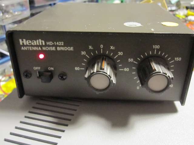
For this measurement, I used an SDR (Software Defined Radio) as the measurement device. In this case an SDR-14. To generate RF I used a noise bridge.

The output of the noise bridge is a good source of wide-band RF.

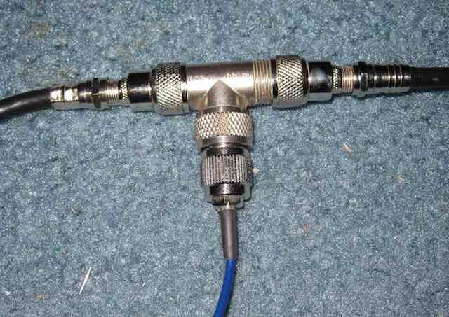
Here is the Tee. On the left is the RF signal, on the bottom is the connection to the SDR, on the right is the open stub.

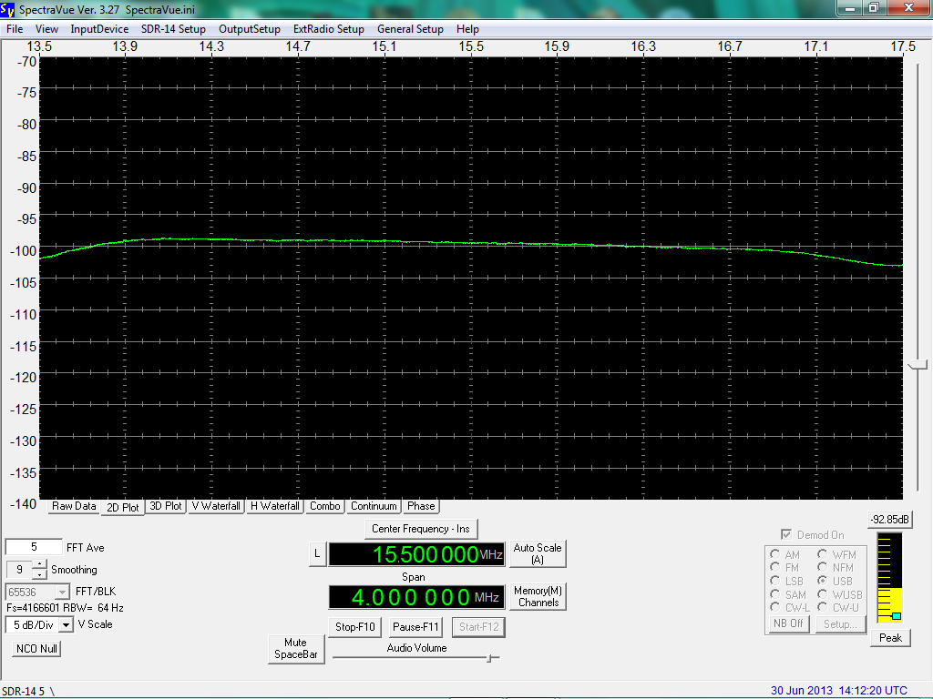
With the noise bridge connected, but no stub, here is what the SDR spectrum looks like, click to enlarge:

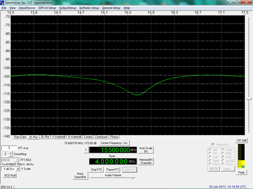
As you can see it is relatively flat. Next, we’ll connect the 1/4 stub (again, click to enlarge):

You can see the dip in the signal level, caused by the stub.

In this case, the stub was 13 ft (4 meters) of cable. Iif the velocity factor was 1.00 the wavelength would be 16 meters, the frequency 18.75 MHz. The frequency of the center of the notch is 15.7 MHz, so the measured velocity factor is 15.7 / 18.75 = 0.84.

Next I used a 9 ft 3 inch (2.85 meter) cable. The wavelength for a velocity factor of 1.00 would be 11.38 meters, the frequency 26.35 MHz. The frequency of the center of the notch was 21.8 MHz, so the measured velocity factor is 0.83.

Using both cables, the total length is 6.85 meters, the wavelength for a velocity factor of 1.00 would be 27.4 meters, the frequency 10.95 MHz. The frequency of the center of the notch was 9.1 MHz, so the measured velocity factor is 0.83.

For this piece of coax, the velocity factor seems to be 0.83, which is a reasonable value.

Building the STM32F4 DISCOVERY Toolchain For Mac OS X

The STM32F4 DISCOVERY is a very neat development board for the STM32 F4 series microcontroller. Not only is it neat, but also cheap. As in $14.55. Here’s the link to buy one from Mouser.

I have some radio related projects that I plan on implementing with this unit. But first I had to get the Open Source development tools installed. And while there are numerous webpages that describe how to do this, none of them actually worked. Such is the world of Open Sores.

With a bit of help, I was able to get things up and running. To save others grief, I’m documenting what I did to get things working. First, a brief description of what goodies you get with this development board.

Here’s a datasheet for the development board.

Some of the Features:
■ STM32F407VGT6 microcontroller featuring 32-bit ARM Cortex-M4F core, 1 MB Flash, 192 KB RAM in an LQFP100 package
■ On-board ST-LINK/V2 with selection mode switch to use the kit as a standalone ST- LINK/V2 (with SWD connector for programming and debugging)
■ Board power supply: through USB bus or from an external 5 V supply voltage
■ External application power supply: 3 V and 5 V
■ LIS302DL, ST MEMS motion sensor, 3-axis digital output accelerometer
■ MP45DT02, ST MEMS audio sensor, omni-directional digital microphone
■ CS43L22, audio DAC with integrated class D speaker driver
■ Eight LEDs:
– LD1 (red/green) for USB communication
– LD2 (red) for 3.3 V power on
– Four user LEDs, LD3 (orange), LD4 (green), LD5 (red) and LD6 (blue)
– 2 USB OTG LEDs LD7 (green) VBus and LD8 (red) over-current
■ Two push buttons (user and reset)
■ USB OTG FS with micro-AB connector
■ Extension header for all LQFP100 I/Os for quick connection to prototyping board and easy probing

Now for the gory details of actually getting all this to work:

First, my system:

I installed this on a Mac Book Pro running Mac OS X 10.6.8. I wanted it on a laptop so I could take it to my basement workshop to do the actual development work. You can do this under linux and Windows as well. I don’t have any information on doing that, you’re on your own. Good luck.

I installed Xcode 4.2, which is the latest version that will run on 10.6 Snow Leopard. I understand that Xcode 4 is required to get the development stuff up and running, I do not know that for a fact, however.

First you need to install a bunch of stuff:
brew install mpfr gmp libmpc texinfo libusb-compat libftdi wget

This uses Homebrew, which you must install if you don’t already have it.

This toolchain script was used as the base: https://github.com/ehntoo/summon-arm-toolchain

As I said earlier, it does not quite work out of the box.

A big thanks to Gwynne who came up with a patch.

So all you need to do is:

cd && git clone git://github.com/ehntoo/summon-arm-toolchain.git && cd summon-arm-toolchain && wget -O - http://darkrainfall.org/build-openocd.patch | patch -p1 && ./summon-arm-toolchain

Then… wait. A while. It takes 20-30 minutes to build everything. Go have lunch.

All of the dev tools are put into ~/sat so make sure that is in your $PATH variable:
export PATH="$HOME/sat:$PATH"

Plug in the dev board and connect to it with the On Chip Debugger:
openocd -f board/stm32f4discovery.cfg

if all goes well, a bunch of text is spit out into the terminal window, ending with:
Info : stm32f4x.cpu: hardware has 6 breakpoints, 4 watchpoints

Then open up another terminal window and connect to the On Chip Debugger:
telnet localhost 4444

Next I grabbed the STM32 Discovery firmware files, to get some sample code:
git clone https://github.com/nabilt/STM32F4-Discovery-Firmware.git

I decided to try the IO_Toggle project first, which turns some digital outputs, connected to LEDs on the board, on and off. Toggling LEDs is the microcontroller version of a Hello World program.

Building the project did not go completely smoothly. I needed to change a line in the Makefile dealing with floating point:
MCFLAGS = -mcpu=$(MCU) -mthumb -mlittle-endian -mfpu=fpv4-sp-d16 -mfloat-abi=hard -mthumb-interwork
to
MCFLAGS = -mcpu=$(MCU) -mthumb -mlittle-endian -mfpu=fpv4-sp-d16 -mfloat-abi=softfp -mthumb-interwork

I don’t yet have a good explanation as to the need to make the change, but I saw it mentioned on many websites while searching for a solution to the problem.

The result is a demo.elf file which gets downloaded to the dev board.

Open up yet another terminal window (while in the directory containing demo.elf) and run gdb via:
arm-none-eabi-gdb

In the OCD telnet window, stop the program currently running on the microcontroller:
reset halt

Then in the window running gdb:
target extended localhost:3333
load demo.elf

Then in the OCD telnet window run the program:
reset run

I was rewarded with blinking LEDs. I then edited the main.c source code to change their toggle rate, and re-built the project, as a test, which all worked.

Next step, some radio related programming!

Decoding ADS-B Aircraft Transponders: An SDR for $17 – The R820T USB RTL-SDR DVB-T Dongle – Part 3

Please be sure to read Part 1 and Part 2, if you’re new to this series of articles.

All aircraft contain a piece of avionics technology called a transponder. This contains a receiver, and a transmitter. When the signal from ground radar is received, the transponder transmits a short burst on 1090 MHz, encoded with information.

There are several possible replies from an aircraft transponder:

  • Mode A replies with a target ID code
  • Mode B replies with the barometric altitude of the plane
  • Mode S, also called the Extended Squitter, is the one we’re interested in.

Mode S, also called ADS-B allows a variety of types of data to be sent from the transponder, including:

  • ICAO aircraft code (the tail number of the plane can be obtained from this)
  • Flight Number
  • Altitude
  • Location (Longitude and Latitude)
  • Heading

There’s an online document called ADS-B for Dummies that goes through the various messages, and their format.

Since the RTL dongles can receive 1090 MHz at a wide bandwidth, it turns out to be possible to use them as low cost transponder decoders. Very low cost. You can pick them up for around $15 on eBay. Dedicated ADS-B receiver packages are more. Much more. As in hundreds of dollars.

There are quite a few packages out for the RTL dongles that decode ADS-B transmissions. For Windows, there’s ADSB#:

For linux and Mac OS X, there’s Dump1090

I compiled Dump1090 for Mac OS X, here is what the output looks like:

The columns across the screen:

  • Hex – the ICAO code for the plane
  • Flight – flight number
  • Altitude – altitude in feet
  • Speed – speed in mph
  • Lat – latitude of position
  • Lon – longitude of position
  • Track – heading in degrees
  • Messages – the number of messages from this plane that have been received
  • Seen – how long ago (in seconds) since the last message from the plane, that is, how long since it has been last seen (or heard from)

I’ve since ported the Dump1090 code over to Cocoa on Mac OS X, resulting in Cocoa1090:

Cocoa1090 uses the ICAO hex code to derive the tail number (and aircraft model) from a database in a text file, which are also displayed.

A beta version of Cocoa1090 can be downloaded here: http://www.blackcatsystems.com/software/cocoa1090.html

An SDR for $17 – The R820T USB RTL-SDR DVB-T Dongle – Part 2

Earlier, I wrote about the RTL2832U based USB TV tuner dongles that can be turned in an inexpensive Software Defined Radio (SDR). Please take a moment to read that for an overview of these insanely great (for the price) modules, if they’re new to you. I’ve since mounted the dongle in a small metal enclosure:

There were two reasons for this, first to reduce noise pickup, the second was to easily add an F style antenna connector.

Next, I wanted to try getting the rtl-sdr series of command line programs to run. I had tried a set of pre built binaries, but they didn’t work, so I decided to build it myself.

First I got the code from http://cgit.osmocom.org/cgit/rtl-sdr/

I followed the instructions from http://sdr.osmocom.org/trac/wiki/rtl-sdr
cd rtl-sdr/
autoreconf -i
./configure
make
sudo make install
sudo ldconfig

The first problem was after ./configure, namely:
configure: error: Package requirements (libusb-1.0 >= 1.0) were not met:

Turns out I had an ancient version of libusb.
sudo port install libusb
solved that.

With the programs built, the next step was running rtl_test:
$ rtl_test -t
Found 1 device(s):
0: ezcap USB 2.0 DVB-T/DAB/FM dongle

Using device 0: ezcap USB 2.0 DVB-T/DAB/FM dongle
Found Rafael Micro R820T tuner
Supported gain values (29): 0.0 0.9 1.4 2.7 3.7 7.7 8.7 12.5 14.4 15.7 16.6 19.7 20.7 22.9 25.4 28.0 29.7 32.8 33.8 36.4 37.2 38.6 40.2 42.1 43.4 43.9 44.5 48.0 49.6
No E4000 tuner found, aborting.

So far so good.

Next I tried running rtl_fm, which lets you demodulate a FM signal. AM is supposedly also supported. I say supposedly because I could not get rtl_fm to work properly. It would run, and write demodulated sound data to a file, but playing it back always produced gibberish. Also, the files were way too large for the specified sample rate and length of time the program was running. The documentation for rtl_fm is sketchy, even by open sores standards. For example, the list of options includes:
[-s sample_rate (default: 24k)]

which naturally makes you suspect -s sets the sample rate. It does no such thing, it actually sets the IF bandwidth. Again, supposedly.

After several hours of trying to get rtl_fm to work properly, I threw in the towel, and moved on to rtl_tcp, which acts as a little TCP server, sending I/Q data to a connected client. I had much better luck here. Running the program produced the following:
$ ./rtl_tcp
Found 1 device(s).
Found Rafael Micro R820T tuner
Using ezcap USB 2.0 DVB-T/DAB/FM dongle
Tuned to 100000000 Hz.
listening...
Use the device argument 'rtl_tcp=127.0.0.1:1234' in OsmoSDR (gr-osmosdr) source
to receive samples in GRC and control rtl_tcp parameters (frequency, gain, ...).

I then connected to it via telnet in another console window:
$ telnet 127.0.0 1234

And the rtl_tcp server program responded with:
client accepted!
and proceeded to send I/Q data to my telnet session, which spewed it to the window. Mission accomplished.

Next I wrote a small program to open a connection to the rtl_tcp server, and grab all the received data, count the number of bytes per second, and display it once per second, as a quick and dirty test to see if everything was working OK. I got around 4M bytes per second, which is correctly for a 2 MHz sample rate (the data is 8 bit I/Q, so there are two bytes per sample).

Having accomplished this, the next step was to make some use of the data. I thought trying to decode and display ADS-B aircraft transponder messages on 1090 MHz would be fun. That is my next post.

An SDR for $17 – The R820T USB RTL-SDR DVB-T Dongle

You may have heard of the latest SDR craze to hit the radio hobby – the RTL based USB dongle TV tuners. These were originally made to receive and decode the European standard digital television broadcasts. An enterprising hobbyist discovered that they can be tuned throughout the VHF and UHF range, and that you can get at the raw sampled data from the onboard A/D converter (only 8 bit, however). This allows them to be used as a very inexpensive Software Defined Radio (SDR) for VHF and UHF. How inexpensive? Mine was $17 shipped, although you can find them for even less, if you’re willing to get them direct from China and wait a few weeks for delivery.

Here is what I got:

There’s the dongle itself, as well as the small (about 4″) antenna.

It’s interested to note that the enclosure actually says SDR on it, the word has apparently gotten out about the SDR applications for this dongle, and someone is private branding them.

Here’s what the inside looks like:

The USB connector is on the left, the MCX style RF connector is on the upper right.

There are control programs available for Windows, Mac OS X, and Linux. For software, first I decided to try rtl-sdr I copied the libraries to the specified locations, restarted, and was greeted with:

>:rtlsdr_osx cps$ rtl_test -t
Found 1 device(s):
0: ezcap USB 2.0 DVB-T/DAB/FM dongle

Using device 0: ezcap USB 2.0 DVB-T/DAB/FM dongle
Failed to open rtlsdr device #0.

It’s possible this is an older version of the rtl-sdr package, that expects the E4000 tuner chip. (Although a less cryptic error message would sure be helpful)

Then I tried Cocoa Radio. It crashes on launch. So far open sores is zero for two.

So next I tried the Mac OS X port of gqrx. Much better! It came right up, and within a minute I was receiving FM broadcast stations. I have noticed that if I make a change to the sample rate, I need to quit and re-start the app before putting it into run mode, or it crashes.

The sensitivity is not bad, I was able to pick up stations about 50 or 60 miles away using the included tiny 4″ antenna, laying on my desk.

Below is a screenshot of gqrx running on the FM band, you can see three FM broadcast stations, at 97.9, 98.5 and 99.1 MHz, the latter is tuned in for demodulation.:

I was also able to pick up 2m packet radio transmissions on 144.39 MHz, and one of the NOAA weather radio stations, on 162.525 MHz.

There are many varieties of these TV tuner dongles out there, mostly the difference is the RF tuner chip used. Previously the E4000 tuner was the preferred one for SDR applications, as it had the widest tuning range, although with a gap in the middle. It apparently is no longer made and is difficult to find tuners that use it. Currently the R820T tuner chip seems to be the preferred one for SDR use, the tuning range is slightly less, but there is no gap. Some eBay vendors identify the chip used, many do not, but there are lists online of the various USB dongles by brand name and model number, with the tuner chip specified, such as here.

My next project was mounting the dongle in a small metal enclosure, with a different RF connector, so I can easily connect one of my existing outdoor antennas to it. Read all about it here.

Measuring The Distance To A Shortwave Radio Station

   HF Weather Fax     
   For Android     

In a previous post, I showed how it was possible to crudely measure the speed of light (or at least another type of electromagnetic radiation, radio waves, in this case) by measuring the time delay between two shortwave radio time stations, WWV and WWVH.

I’ve decided to re-do that experiment, but in a slightly different way. Rather than measure the speed of propagation, I will use that speed to determine the distance to the radio station.

Various time stations transmit precise time on several shortwave frequencies. Here in the USA, we have WWV in Ft. Collins, Colorado, which transmits on 2.5, 5, 10, 15, and 20 MHz. We also have WWVH in Kekaha, Hawaii, which transmits on 2.5, 5, 10, and 15 MHz. These stations transmit an audio “tick” at exactly each UTC second. There is also the Canadian station CHU, located near Ottawa, Ontario, which transmits on 3330, 7850, and 14670 kHz.

One way to measure the speed of radio waves (and light) would be to measure how long it takes for the tick to travel a fixed distance. Divide the distance by the time, and we have the speed of light. However, that requires knowing the exact UTC time locally. This can be done with a GPS unit that outputs a 1 PPS (pulse per second) signal.

How to feed these signals into the computer, so they can be measured? The radio audio is easy enough, feed it into the sound card. It turns out the 1 PPS signal can also be fed into the sound card, on the other channel. I used a capacitor to couple it.

The first measurement that is required is one to determine what time delay is added by the radio electronics. In my case, I was using a JRC NRD 545 receiver, which has DSP (Digital Signal Processing) to implement the audio filters. This certainly adds a time delay. I therefore needed to run some baseline measurements, to determine how long this delay was.

I fed the same 1 PPS signal into the antenna jack of the radio. The signal is a short (10 microsecond pulse) that is rich in harmonics, so it produces a noticeable “tick” sound every second. I then recorded the audio from the radio, along with the 1 PPS signal fed into the other channel, and obtained this data (click on the graph to enlarge it):

I measured the time delay between the two ticks, and found it to be 286 samples. At 44.1 kHz, each sound sample is 22.676 microseconds. Multiplication gives us the time delay, namely 6485 microseconds. This delay added by the radio is constant, provided I do not adjust the IF filtering parameters (which were set to USB mode, 4.0 kHz wide, for all tests).

Next, the antenna was reconnected, an the radio tuned to 15 MHz. At this time of the day (about 2100 UTC) it is possible to hear both WWV and WWVH. Here’s the sound recording:

The WWV pulse occurs at about 5.18 seconds on the recording, and WWVH, much weaker and harder to see, at about 5.2 seconds.

The delay for the WWV pulse is 657 samples. Subtracting the radio delay of 286 gives us a delay due to propagation of 371 samples. Multiplying by our conversion factor of 22.676 microseconds per sample gives us 8413 microseconds.

Light (and radio waves) travel at 186,282 miles per second or about 0.186 miles per microsecond. For the metric inclined, that’s 299.792 km/sec or 0.300 km per microsecond. So multiplying our time in microseconds by the distance light travels each microsecond gives us the distance:

8413 * 0.186 = 1567 miles (2522 km)

The actual distance, along the Earth’s surface, from my location to WWV is 1480 miles, or 2382 km. Why the discrepancy? The radio waves do not travel along the Earth’s surface, but instead are reflected from the ionosphere, which is several hundred miles up. This means the actual path they take is longer. We’ll try to take that into account, a little further down.

The delay for the WWVH pulse is 1550 samples. Subtracting the radio delay of 286 gives us a delay due to propagation of 1264 samples. Multiplying by our conversion factor of 22.676 microseconds per sample gives us 28662 microseconds. We’ll do our next multiplication again, to convert to distance:

28662 * 0.186 = 5339 miles (8592 km)

The actual distance from my location to WWVH is 4743 miles, or 7633 km.

Next, here’s a recording from the Canadian time station, CHU:

The delay for the CHU pulse is 401 samples. Subtracting the radio delay of 286 gives us a delay due to propagation of 115 samples. Multiplying by our conversion factor of 22.676 microseconds per sample gives us 2607 microseconds. We’ll do our next multiplication again, to convert to distance:

2607 * 0.186 = 486 miles (782 km)

The actual distance from my location to CHU is 407 miles, or 656 km.

Now let’s try to take into account the actual path of the radio waves, which get reflected off the ionosphere. We need to know the height of the ionosphere, which unfortunately is not constant, nor is it the same over each part of the Earth. Here is a map showing the approximate height, while the above recordings were taken:

In the case of the path to CHU, the height is about 267 km, or 166 miles.

We also need to determine the straight line path between my location and CHU, through the Earth, vs the distance along the Earth’s surface. This can be calculated, and it is 391 miles, or 629 km.

We’ll determine what the actual path length is for a radio signal traveling this distance. It looks like a triangle, with a height of 166 miles, and a base of 391 miles. We need to determine the other two sides to find the total path length. All we need to do is take half of 391 miles, which is 195.5 miles, square it, add to that 166 squared, and take the square root, then double our answer. The result is 513 miles, which is very close to our measured value of 486 miles. We’re off by a little more than 5%.

Next let’s try WWV: The actual distance is 1468 miles or 2362 km. Doing our math, using an approximate FoF2 ionosphere height of 246 km (153 miles): Half of 1468 miles is 734 miles, we square that and add to 153 squared, and take the square root, and double our answer, getting 1500 miles. Our measured distance was 1567 miles, so we’re off by less than 5%.

Next, the case of WWVH. This is more complicated, as the signal probably is making more than one “hop”, that is, it is going up to the ionosphere, reflected down to Earth, and then reflected back up again, and down again. This may possibly occur multiple times.

We’ll try doing the math anyway. The actual distance is 4588 miles or 7383 km. Doing our math, using an approximate FoF2 ionosphere height of 253 km (157 miles): Half of 4588 miles is 2294 miles, we square that and add to 157 squared, and take the square root, and double our answer, getting 4598 miles. Our measured distance was 5339 miles, an error of 16%. But again, we don’t know how many hops there were. Still, not a bad effort.

Does anyone else have a GPS receiver with a 1 PPS output? If so, I’d like to hear from you, I have some additional experiments in mind.

Adding a Rubidium Reference to the netSDR

I recently acquired a FE-5680 rubidium frequency reference off eBay. This is a high stability 10 MHz frequency reference. I also bought the REFCLOCK option for the netSDR directly from RF-Space, which takes the 10 MHz as a reference input, and produces an 80 MHz clock for the A/D, locked to the reference input. The result is less drift in the radio. The stock netSDR drift is already extremely low, but I want to do some observations of RF carriers over a long time period, so I wanted to reduce the drift even further.

Here’s a picture of the reference I bought, it was around $55 shipped, from China of course.

The reference requires 16V at just under 2A peak, as well as 5V at a lower current. I used an old laptop power supply, and rigged a 7805 to produce the 5V. Unfortunately all input and output is via a DB-9 connector. The 16V is applied via the barrel connector on the left, and the 10 MHz comes out the BNC on the right.

Here’s the inside of the netSDR receiver:

And after installing the REFCLOCK module:

I’ll post some followup articles with long term waterfalls, and we’ll see how the drift looks.

But how does the rubidium frequency reference work? From the FE-5680 technical manual:

The Rubidium Physics Package incorporates a rubidium cell, rubidium lamp, and servo electronics to utilize the ground-state hyperfine transition of the rubidium atom, at approximately 6.834x GHz.The VCXO is locked to the rubidium atomic resonance in the following manner. The VCXO frequency of 50.255x MHz is an exact sub-multiple (36) of the atomic resonance frequency at 6.834x GHz. A microwave signal, having a frequency in the vicinity of 6.834x GHz, is generated from the nominal 50.255x MHz VCXO input. This microwave signal is used to resonate vaporized rubidium atoms within a sealed glass Rb resonance cell that is placed in a low Q microwave cavity.

The microwave frequency generation method is designed so that the VCXO frequency is exactly 50.255x MHz when the microwave frequency is exactly equal to 6.834x GHz. The frequency of the signal applied to the microwave cavity can be maintained equal to 6.834x GHz by generating an error signal when the frequency varies, and using this error signal to servo the VCXO via its control voltage.

The error signal is generated in the physics package. Light from the rubidium lamp, produced by an excited plasma discharge, is filtered and passed through the rubidium resonance cell where it interacts with rubidium atoms in the vapor. After passing through the resonance cell, this light is incident upon a photocell. When the applied microwave frequency is equal to 6.834x GHz, the rubidium atoms are resonated by the microwave field in the cavity; this causes the light reaching the photocell to decrease. The decrease in light, when the microwave frequency is equal to the sharply defined Rubidium frequency, is then converted electronically to an error signal with phase and amplitude information that is used to steer the VCXO via its control voltage and keep it on frequency at 50.255x MHz.

The VCXO operates nominally at 50.255x MHz. The VCXO has two isolated outputs; one output is provided to the Rubidium Physics Package for comparison purposes, and the other output is used as the clock input for direct digital synthesis within the Synthesizer.

An AD8307 Based RF Meter

The AD8307 IC is advertised as being a “Low Cost, DC to 500 MHz, 92 dB Logarithmic Amplifier”. This is a block diagram:
AD8307 Block Diagram

From the AD8307 datasheet: The essential purpose
of a log amp is not to amplify, though amplification is utilized to
achieve the function. Rather, it is to compress a signal of wide
dynamic range to its decibel equivalent. It is thus a measurement
device. A better term may be logarithmic converter, because its
basic function is the conversion of a signal from one domain of
representation to another via a precise nonlinear transformation.

And here’s a basic AD8307 circuit, mine is similar:
AD8307 Circuit

In my case, I have an LC filter on the incoming DC power, as well as the outgoing DC signal level, to reduce noise pickup. My meter is built into a small paint can, on the underside of the lid, which works as an excellent ground plane:
RF Meter

And here is the top of the lid, mounted on the can:
RF Meter
The toggle switch isn’t being used. I was going to power the meter off of a 9 volt battery to further reduce noise, but comparison tests between the battery and DC power supply showed no difference.

The output of the meter is a voltage proportional to the input power, measured in dBm. Zero volts is output for −84 dBm,
corresponding to a sine amplitude of 20 μV. There is a noise floor, and the specified range of the AD8307 is −74 dBm to +16 dBm. The output voltage increases by 25 mV for each dBm increase in RF input.

DDS-60 Direct digital synthesizer

Recently I put together a DDS-60. DDS stands for Direct Digital Synthesizer. It is a way to generate arbitrary frequencies. Samples are fed to a D/A (Digital to Analog Converter) at a fixed clock rate (in this case 180 MHz derived from a 30 MHz oscillator). These samples are generated by a NCO (Numerically Controlled Oscillator). Think of it as a sine wave being generated point by point, at a fixed (depending on the ratio of the output frequency to the 180 MHz clock) number of degrees per sample. The output frequency can instantly be changed by just altering this degrees per sample value.

In the case of the DDS-60, any output frequency from 0 to 60 MHz can be generated. AD9851 DDS chip is used. This chip, along with a buffer/amplifier, low pass filter, and voltage regulator is all contained on a small (about one by two inch) board. The output amplitude is set by a small trimmer pot, with a maximum of about 4 volts peak-peak.

Three TTL level digital control lines are used to select the frequency. In my case, I have them connected to the parallel port of a PC.

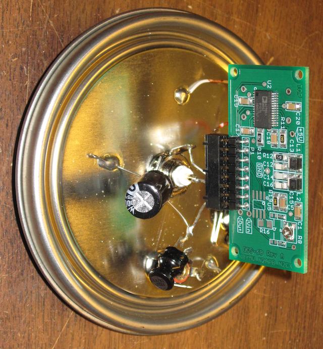
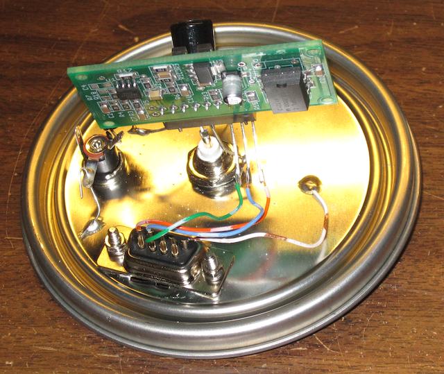
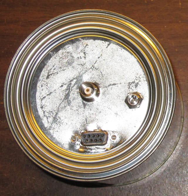
I mounted the DDS-60 on the underside of the lid of a one quart paint can. The output goes to a BNC connector, there is also a 2.5mm barrel jack for 12V DC power, and a 9 pin D-SUB connector for the digital lines to the PC:

DDS-60 Board
There is a small LC filter (about 3 mH and 1000 uF) on the incoming DC power line.

DDS-60 board

Here is the resulting unit. Ugly, but it works!
DDS-60 in tin can

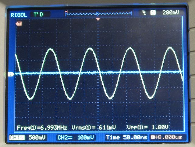
And here is the output on a scope:
DDS-60 output on an oscilloscope

So what can you do with a DDS?

First, it’s a very handy piece of gear for the RF test bench. You have a stable and precise source of RF that can cover the entire LF, MF, and HF bands. One of my next goals is to write some software to do automated testing and sweeps of RF, using an RF voltmeter as the input. I hope to blog about that shortly.

Second, you can use it as an exciter to drive an RF amplifier.