

It’s often handy to have an RF noise generator when testing various circuits, especially filters. I was working on a low pass filter for long wave, and wanted a way to measure the performance of the filter.
This is the noise generator I came up with. It’s a fairly simple circuit:
A zener diode as the noise source. Zener diodes, when conducting a very low current, produce a wide spectrum of noise. In this case I used a 6.8 volt zener diode, similar values should work as well.
A single NPN transistor used to amplify the noise form the zener diode.
A variable resistor to adjust the current through the zener diode for maximum noise.
Three resistors, four capacitors, and an inductor (to filter out noise you don’t want, from the power supply).
In my case, I powered the generator from a 12 volt DC power supply, you could use a 9 volt battery as well, if you wish.
Below is the schematic (you can click on any of the images to see them full sized):
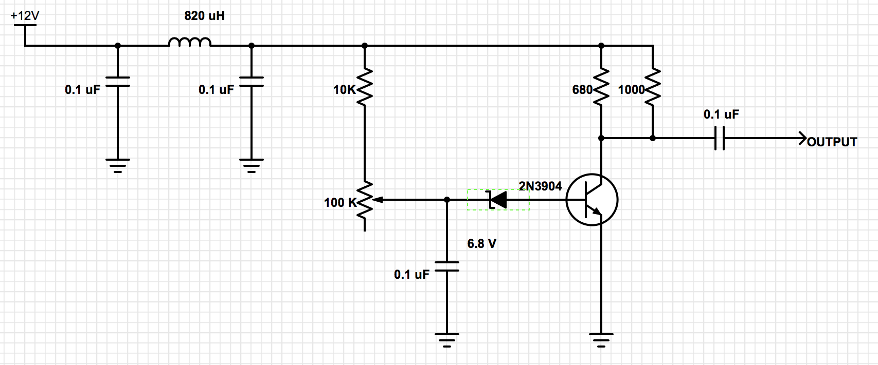
The incoming DC power is filtered by the inductor and two capacitors.
Next it goes through the variable resistor as well as a fixed 10K resistor, so that the maximum current through the zener diode is limited to a safe value during adjustment. The noisy zener diode current is then applied to the base of the transistor, used as a common emitter amplifier. I used a 2N3904, other values should work as well, though you may need to adjust resistor component values. The 0.1 uF capacitor keeps the voltage on the zener diode relative constant.
The 680 and 1000 ohm resistors in parallel are values I had in my parts bin, suitable to use in parallel based on the current to the base of the transistor. The transistor output is the AC coupled through another 0.1 uF capacitor.
Below is a photograph of the circuit, build on the lid of a 1 pint paint can. I have a number of these from geiger tubes that I purchase for use in radiation detectors that you can plug into your computer for experiments as well as long term measurements and graphing. Hey, want to buy one of my geiger counters? Full details are here: http://www.blackcatsystems.com/GM/GeigerCounters.html
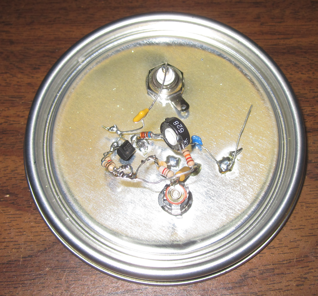
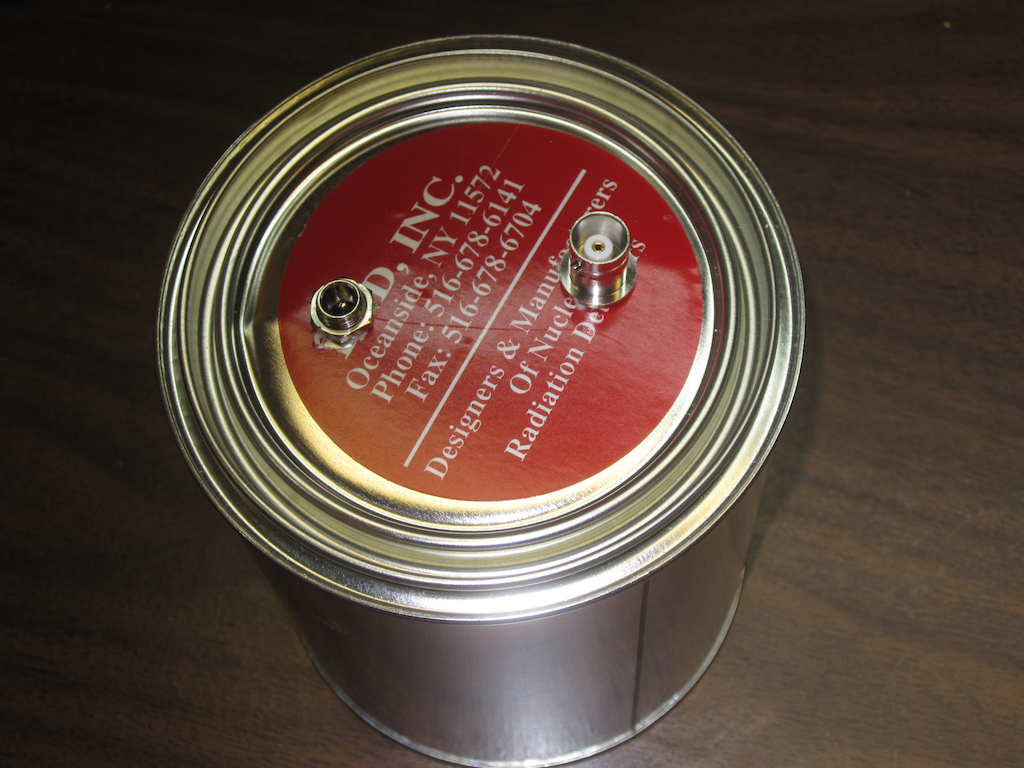
OK, back to the noise generator. The paint can lids are handy for prototyping RF circuits. You can built them dead bug style on the bottom side of the lid, test them out, then put them on the can for your RF shield, as shown below. The two connectors are a BNC jack for the RF output, as well as a standard DC power jack for the power supply.
For looking at the generated noise spectrum, I used the fabulous SdrDx SDR software by Ben, AA7AS, along with an AFE822x SDR.
Below is the noise level with the RF noise generator powered off (you can see an RFI noise source around 1300 kHz from elsewhere in my lab, which I have not yet tracked down):
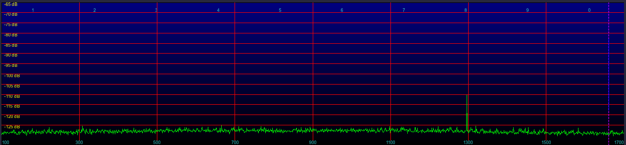
And with it powered on:
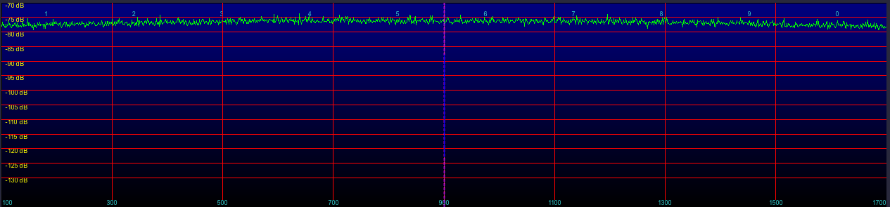
The increase in noise level is about 50 dB, very suitable for testing filters and such.
Pingback: A Low Pass Filter For Longwave | RadioHobbyist.org
Hi.
What peak to peak voltage do you get for your noise circuit please? I’m assuming that you have access to a ‘scope.
Thanks.
Interesting circuit. Is the circuit quite layout dependent I am just playing with one on a breadboard. The one I have is -13dbm at 1mhz but has rolled off to the spectrum analyser noise floor come 50mhz
I’m hoping to do a YouTube video on using a noise source for people without a tracking generator. I have tried a few circuits using LED none worked at all for me. Yours is generating noise but it’s not broadbands.
Here is a link to my channel
https://youtu.be/5XPy5zhCago
Best regards Chris
I think the HF peak at 1.3Ghz sounds like a CPU, most likely the one running SDRdx (try to change the power settings to best performance), but it could be even of something else