Recently, I have been DXing DGPS (Differential GPS) stations on the longwave band. They occupy the region from 285 to 325 kHz. I’ve been getting some pretty good results with some custom software I wrote that demodulates all of the DGPS channels (1 kHz apart) in parallel from I/Q recording files from my SDR. This lets me analyze the entire band from a set of overnight recordings. That itself is the subject of another post I am working on.
I decided to build a low pass filter that just passes the longwave band, attenuating medium wave and shortwave, in an attempt to improve reception of weak DGPS signals.
The filter is flat to about 400 kHz, then starts attenuating. It is down about 30 dB at the start of the MW band (530 kHz) and reaches about 45 dB by 700 kHz, then eventually reaches about 50 dB. My strongest local MW stations are on 1280 and 1320 kHz, so I felt this was sufficient. I did not want to attenuate signals on the longwave band itself.
Below is a schematic of the filter. I used what components I had on hand, hence the paralleling of some of the inductors and capacitors. (Click on any of the images to enlarge them to full size)
I previously wrote about Building an RF Noise Generator For Testing Filters and included some plots showing the noise spectrum taken with an AFE822x SDR running the SdrDx software. Below is a plot of the noise generator fed directly into the SDR over the range of 100 to 1700 kHz.
Next is the spectrum with the filter installed. You can see the dramatic attenuation starting above about 400 kHz. (You can see an RFI noise source around 1300 kHz from elsewhere in my lab, which I have not yet tracked down)
Below you can see the entire MW and LW bands, this is without the filter and using my 500 ft beverage antenna:

Next, with the filter installed. Most of MW is knocked out, except for a few locals and stations on the lower end of the band. 580 is WHP in Harrisburg PA with 50 kW. A few more stages on the filter might be able to attenuate that some more, but I’m pretty happy with things already.
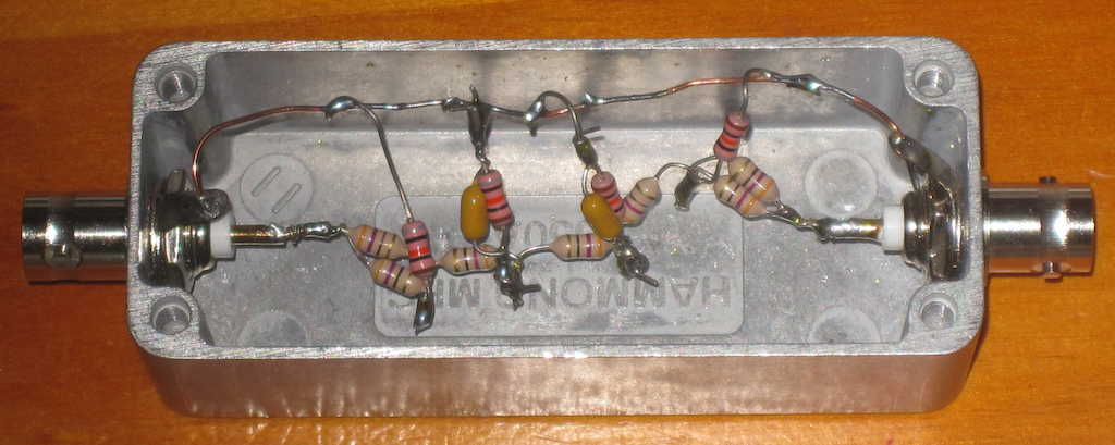
Below is an image of the filter itself, mounted in an aluminum enclosure:
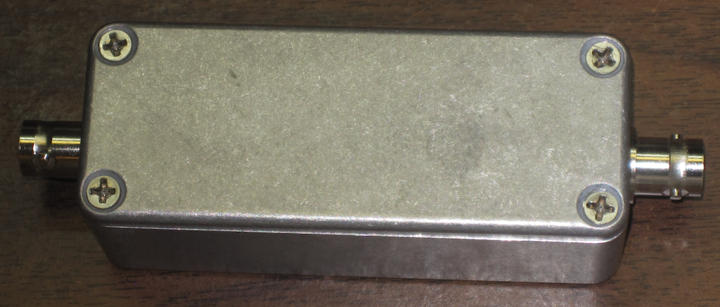
And all bundled up, ready for use:


At last a filter built using cheap axial inductors. In theory it should reach -80dB at 800 kHz. My need was for a filter that would cut off above the MW band and I’ve built one using 10 uH inductors and 2n2 capacitors using the same construction technigue – but in a smaller diecast box that I had to hand. It works very well – the cut off is around 2 MHz and kills the 80/75m band and above. I’ve shared the link and my own construction notes. I estimate -60dB in practice.
Did you feel an improvement in LW reception?