Previously I wrote about the various kinds of transmissions you can heard on the 250 MHz SATCOM satellites. While you can pick these up with a standard scanner antenna, reception is much better with a directional antenna.
This page documents my project to construct a helical antenna for SATCOM listening, 240-270 MHz.
The antenna is based off the design found on this page, which has the specific dimensions and other technical details.
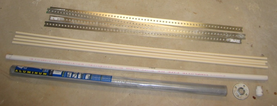
Here are the supplies:
Four 4 ft long strips of steel, four 5 ft long pieces of 1/2″ PVC pipe, one 5 ft long piece of 1 1/4″ PVC pipe for the boom, and window screening for the ground plane.
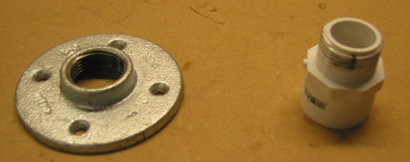
Here’s a close up of the flange and fitting for the PVC boom:
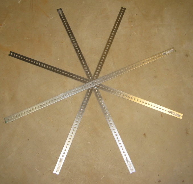
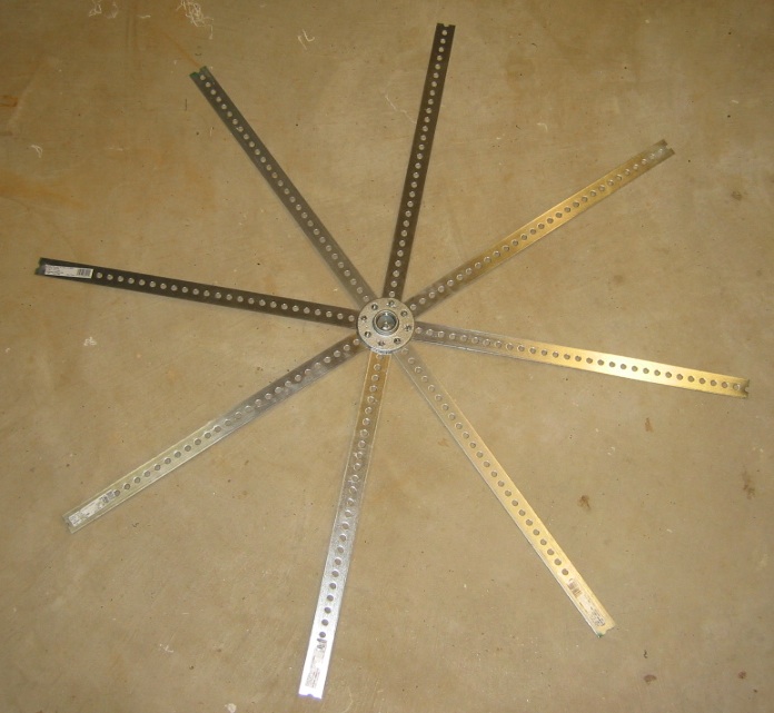
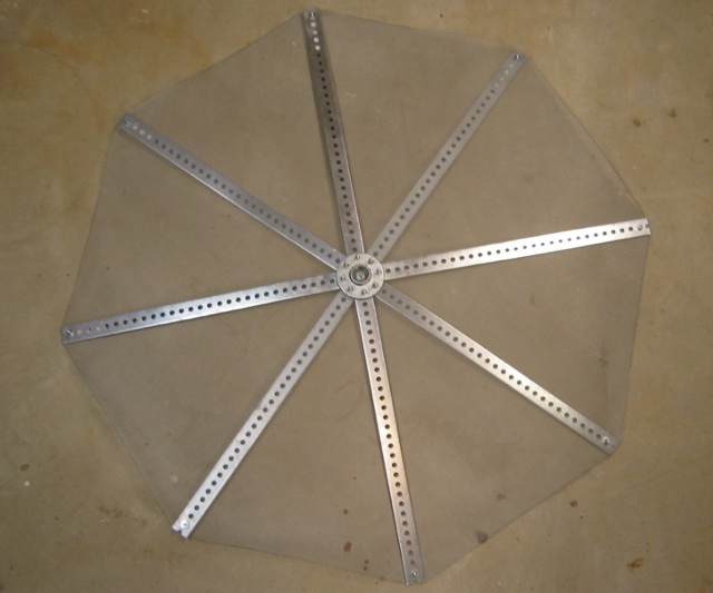
Here are the four steel strips arranged in the radial pattern:
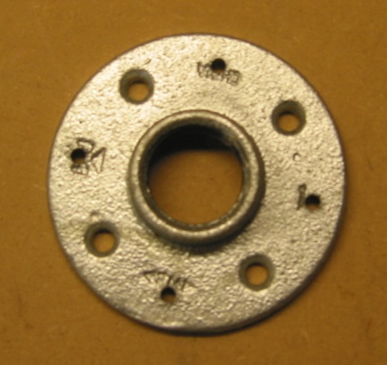
Next I drilled four additional holes in the flange, so it could be screwed to the eight radials:
#10 hardware was used to attach it:
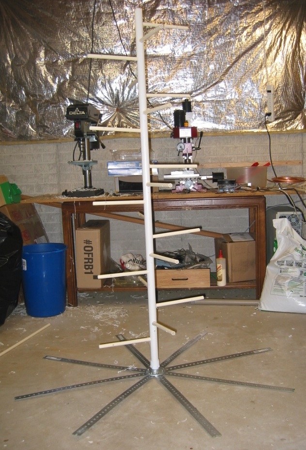
Here it is with the PVC boom attached, to see the overall size:
And now with the 20 supports for the tubing installed:
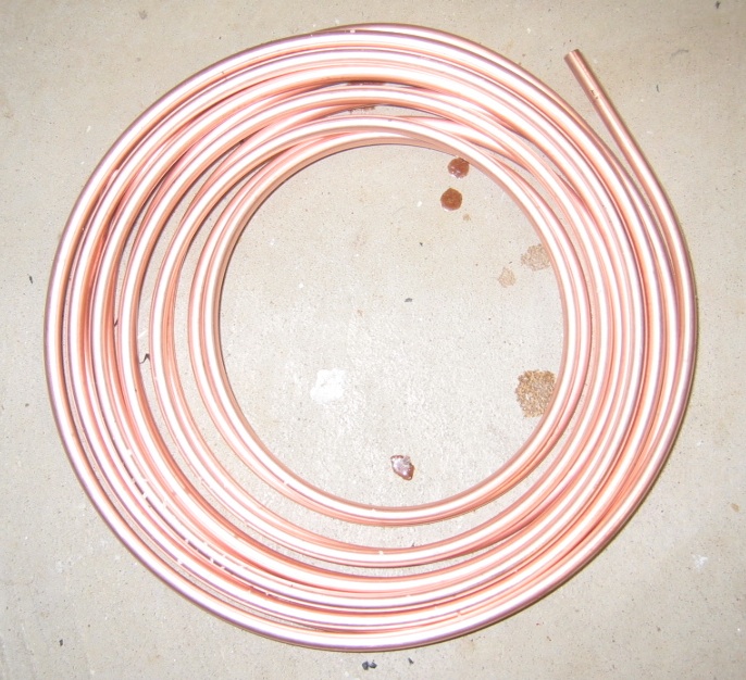
The tubing is 1/4 inch diameter:
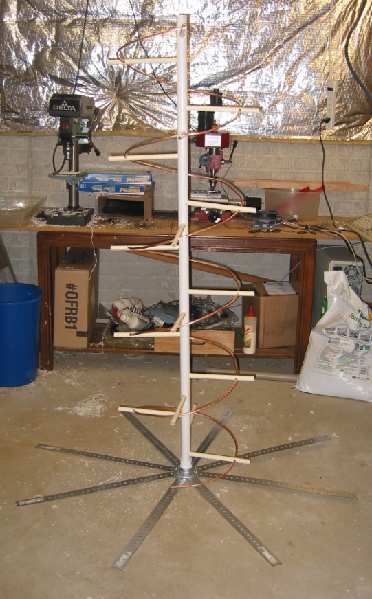
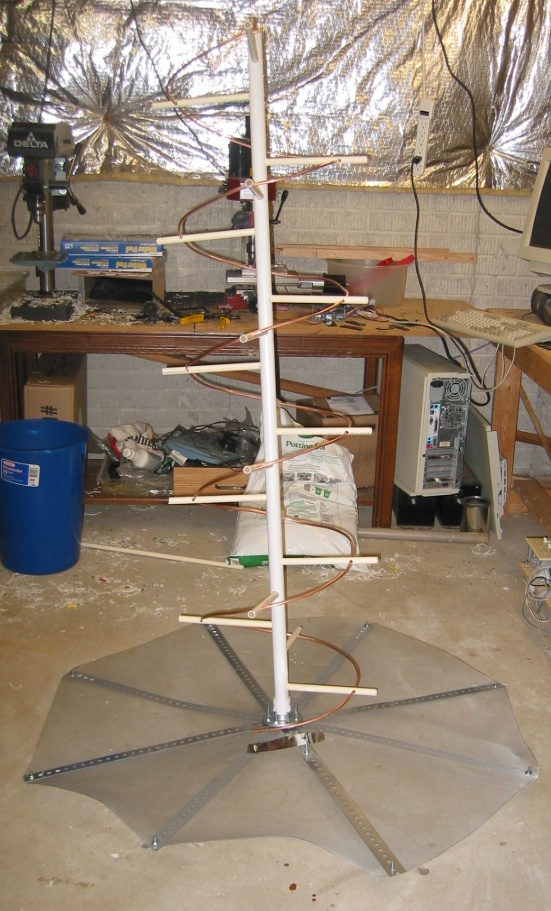
Here it is with the 5 turns of 1/4″ diameter tubing:
The screening has been added to the reflector. It is sandwiched between the strips for support:
The [mostly] assembled helical antenna. The matching section is made from tin-plate and is cut to be a quarter of a turn, about 60mm wide. It’s soldered or bolted to the ground plane at the connector end, and supported by an adjustment screw at the other end. I’ve honestly not noticed much if any difference in the received signal, by fiddling with it. See http://www.uhf-satcom.com/uhf/uhfantenna.html for more details on the matching section.
Final assembly will be done outside, so everything is not tightly fastened yet:
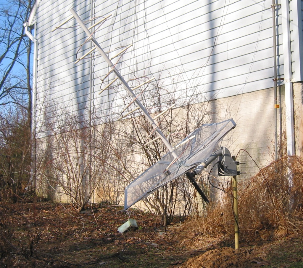
Here it is outside, mounted on a SG-9120 motor. The motor uses the DiSEqC protocol for control, which is sent over standard coax cable. It is a standard in the satellite TV industry.
The motor is controlled by a Moteck digibox, which sits inside the shack:

Another view:

The angle of the motor is adjusted based on the latitude of the receiving site, so that as the motor turns the satellite tracks across the geostationary orbit.
