
There are two characteristics that we’re particularly interested in:
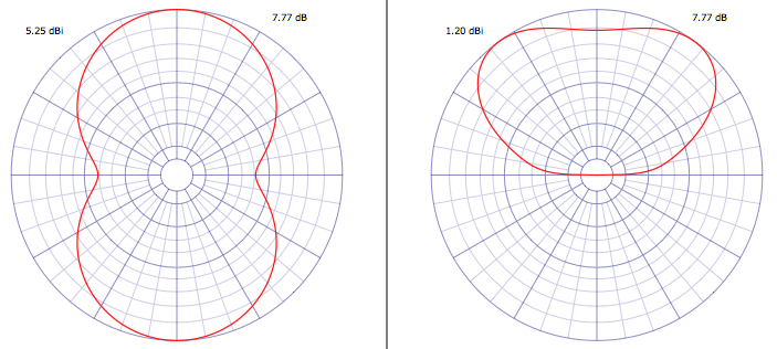
First, the radiation pattern. This describes how well the antenna receives (or transmits) a signal in various directions. Below is the radiation pattern for the standard half wave dipole in “free space”, that is, without a ground below it. You can imagine it is in outer space, or so far above the Earth’s surface that there are no effects from the ground.
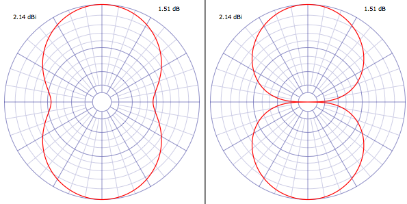
The antenna wire is oriented east/west. The image on the left is the horizontal pattern. Imagine you’re above the antenna, looking down. This is the pattern around the antenna, all 360 degrees of the compass. There are two main lobes, one to the north, and one to the south. This means that the antenna is particularly sensitive to signals to the north and south, and less so to signals to the east and west. For a transmitting antenna, most of the radiated signal is directed the same way. One rule for antennas is that the radiation patterns are the same for both transmitting and receiving.
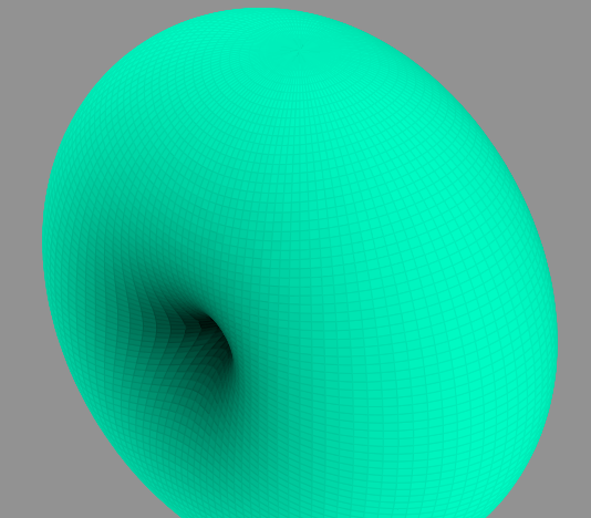
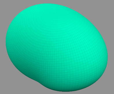
The image on the right is the vertical pattern. Imagine you’re at the same height as the antenna, looking at it. The top of the graph represents the signal strength going up, the bottom going down, etc. In this case, there are two sharp nulls directly to the left and right of the antenna. These are in line with the antenna. What this is telling us is that most of the RF energy is directed around the line containing the antenna wire. Here is what it looks like in 3D:
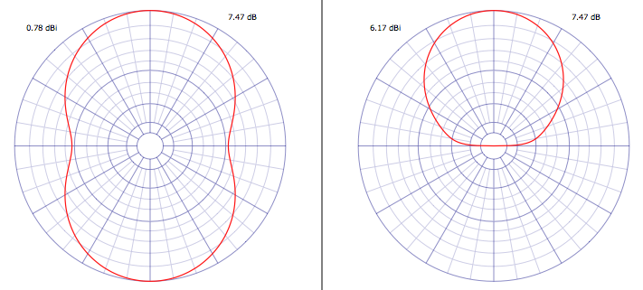
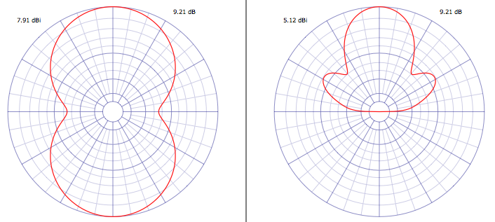
Now let’s make the antenna more realistic by putting it above the ground. In this case, we’re going to put a dipole cut for the 6.9 MHz pirate band 30 feet above the ground, which is probably a typical case for many listeners (and operators). Here’s the resulting radiation pattern:
Here is what it looks like in 3D:
We can think about what happened. The ground obviously blocks reception of radio waves from that direction. Likewise, it absorbs most of the RF energy directed to the ground (some of it is reflected, especially at shallow angles). The resulting antenna pattern is directed upwards.
There’s actually a term for such an antenna – the NVIS – Near Vertical Incident Skywave antenna. Most of the RF energy is directed upwards, where it is then reflected downwards by the ionosphere. Good reception coverage is obtained for a distance of several hundred miles around the antenna, providing the frequency is low enough. If it is too high, the radio waves will pass through the ionosphere without being reflected. NVIS is commonly used below 10 MHz, although higher frequencies are possible with active solar conditions.
Similarly, such an antenna is more sensitive to radio waves coming almost straight down from the ionosphere, that is, from transmitting stations that are several hundred miles away. It’s basic geometry, the more distant the transmitting station is, the lower the angle of radiation.
On the other hand, if you want to reach distant listeners, you need to get more of your radio waves to be directed at a lower angle. If we double the height to 60 feet, here’s what we get:
It’s a significant improvement, but the maximum radiation angle is still pretty high. If we triple the height to 90 feet, here’s what we get:
That may actually be worse! The radiation pattern changes dramatically with height, often in difficult to predict ways.
A horizontal half wave dipole is still a very useful antenna for shortwave radio, especially for transmitting distances of several hundred miles. Further reception is certainly possible, when conditions are good. In the next entry, I’ll take a look at another type of antenna, the vertical.
I’ve been curious about “NVIS”. Thanks.